Kia Picanto (JA): Cylinder Block Assembly / Cylinder Block
Repair procedures
| Disassembly |
|

|

| 1. | Remove the engine and transaxle assembly.
(Refer to Engine and Transaxle Assembly - "Engine And Transaxle Assembly")
|
| 2. | Remove the transaxle assembly from the engine assembly.
(Refer to Manual Transaxle System - "Manual Transaxle")
|
| 3. | Remove the flywheel.
(Refer to Cylinder Block Assembly - "Flywheel")
|
| 4. | Remove the rear oil seal.
(Refer to Cylinder Block Assembly - "Rear Oil Seal")
|
| 5. | Install the engine assembly to engine stand for disassembly. |
| 6. | Remove the cylinder head cover.
(Refer to Cylinder Head Assembly - “Cylinder Head Cover”)
|
| 7. | Remove the thermostat housing.
(Refer to Cooling System - “Thermostat”)
|
| 8. | Remove the timing chain.
(Refer to Timing System - “Timing Chain”)
|
| 9. | Remove the intake manifold.
(Refer to Intake and Exhaust System - "Intake Manifold")
|
| 10. | Remove the turbo manifold module.
(Refer to Intake and Exhaust System - "Turbo Manifold Module")
|
| 11. | Remove the cylinder head.
(Refer to Cylinder Head Assembly - “Cylinder Head”)
|
| 12. | Remove the oil pan and the oil screen.
(Refer to Lubrication System - “Oil pan”)
|
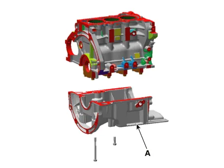
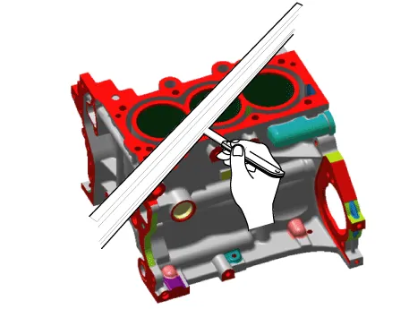
| 13. | Remove the ladder frame (A). Insert
the blade of SST (09215-3C000) between the cylinder block and the
ladder frame and cut out applied sealer. Then, remove the ladder frame.
|

| 14. | Check the connecting rod side clearance.
(Refer to Cylinder Block Assembly - "Piston And Connecting Rod")
|
| 15. | Check the connecting rod cap oil clearance.
(Refer to Cylinder Block Assembly - "Piston And Connecting Rod")
|
| 16. | Remove the piston and connecting rod assemblies.
(Refer to Cylinder Block Assembly - "Piston and Connecting Rod")
|
| 17. | Check the main bearing oil clearance.
(Refer to Cylinder Block Assembly - "Crankshaft")
|
| 18. | Check the crankshaft end play.
(Refer to Cylinder Block Assembly - "Crankshaft")
|
| 19. | Remove the crankshaft.
(Refer to Cylinder Block Assembly - "Crankshaft")
|
| 20. | Remove the water jacket insert.
(Refer to Cylinder block - "Water Jacket Insert")
|
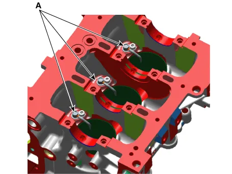
| 21. | Remove the oil jet (A).
|
| Inspection |
| 1. | Remove the gasket material. Using a gasket scraper, remove all the gasket material from the top surface of the cylinder block. |
| 2. | Clean the cylinder block. Using a soft brush and solvent, thoroughly clean the cylinder block. |
| 3. | Inspect the top surface of the cylinder block for flatness. Using a precision straight edge and feeler gauge, measure the surface contacting the cylinder head gasket for warpage.
|
| 4. | Inspect the cylinder bore. Visually check the cylinder for vertical scratches. If deep scratches are present, replace the cylinder block. |
| 5. | Inspect the cylinder bore diameter. Using a cylinder bore gauge, measure the cylinder bore diameter at position in the thrust and axial direction.
|

| Reassembly |
| 1. | Install the oil jet (A).
|
| 2. | Install the water jacket insert.
(Refer to Cylinder block - "Water Jacket Insert")
|
| 3. | Install the crankshaft.
(Refer to Cylinder Block Assembly - "Crankshaft")
|
| 4. | Check the crankshaft end play.
(Refer to Cylinder Block Assembly - "Crankshaft")
|
| 5. | Check the main bearing oil clearance.
(Refer to Cylinder Block Assembly - "Crankshaft")
|
| 6. | Install the piston and connecting rod assemblies.
(Refer to Cylinder Block Assembly - "Piston and Connecting Rod")
|
| 7. | Check the connecting rod cap oil clearance.
(Refer to Cylinder Block Assembly - "Piston And Connecting Rod")
|
| 8. | Check the connecting rod side clearance.
(Refer to Cylinder Block Assembly - "Piston And Connecting Rod")
|
| 9. | Install the ladder frame.
|


| 10. | Assemble the remaining parts in the reverse order of disassembly.
|
Repair procedures Disassembly • Use fender covers to avoid damaging painted surfaces.• To avoid damaging the cylinder head, wait until the engine coolant temperature drops below normal temperature (20°C [68°F]) before removing it.
Components and components location Components 1. Cylinder head gasket 2. Cylinder head 3. Intake oil control valve (OCV) 4. Exhaust oil control valve (OCV) 5.
Other information:
Kia Picanto (JA) 2017-2026 Service & Repair Manual: Rear Combination Lamp
Repair procedures Removal 1.Disconnect the negative (-) battery terminal. 2.Remove the rear combination lamp (A) after loosening the screws. 3.Remove the rear combination lamp packing (A). 4.Disconnect the rear combination lamp connector (A).
Kia Picanto (JA) 2017-2026 Service & Repair Manual: Smart Key Diagnostic
Repair procedures Inspection Self Diagnosis With Scan Tool It will be able to diagnose defects of SMART KEY system with KDS/GDS quickly. KDS/GDS can operates actuator forcefully, input/output value monitoring and self diagnosis. The following three features will be major problem in SMART KEY system.
Categories
- Manuals Home
- Kia Picanto Owners Manual
- Kia Picanto Service Manual
- Heating,Ventilation, Air Conditioning
- Engine Control / Fuel System
- Brake System
- New on site
- Most important about car
