Kia Picanto (JA): Cylinder Block Assembly / Crankshaft
Repair procedures
| Disassembly |
|

|

| 1. | Remove the engine and transaxle assembly.
(Refer to Engine and Transaxle Assembly - "Engine And Transaxle Assembly")
|
| 2. | Remove the transaxle assembly from the engine assembly.
(Refer to Manual Transaxle System - "Manual Transaxle")
|
| 3. | Remove the flywheel.
(Refer to Cylinder Block Assembly - "Flywheel")
|
| 4. | Remove the rear oil seal.
(Refer to Cylinder Block Assembly - "Rear Oil Seal")
|
| 5. | Install the engine assembly to engine stand for disassembly. |
| 6. | Remove the cylinder head cover.
(Refer to Cylinder Head Assembly - “Cylinder Head Cover”)
|
| 7. | Remove the thermostat housing.
(Refer to Cooling System - “Thermostat”)
|
| 8. | Remove the timing chain.
(Refer to Timing System - “Timing Chain”)
|
| 9. | Remove the intake manifold.
(Refer to Intake and Exhaust System - "Intake Manifold")
|
| 10. | Remove the turbo manifold module.
(Refer to Intake and Exhaust System - "Turbo Manifold Module")
|
| 11. | Remove the cylinder head.
(Refer to Cylinder Head Assembly - “Cylinder Head”)
|
| 12. | Remove the oil pan and the oil screen.
(Refer to Lubrication System - “Oil pan”)
|
| 13. | Remove the ladder frame.
(Refer to Cylinder Block - “Cylinder Block”)
|
| 14. | Remove the piston and connecting rod assemblies.
(Refer to Cylinder Block Assembly - "Piston and Connecting Rod")
|
| 15. | Check the main bearing oil clearance. |
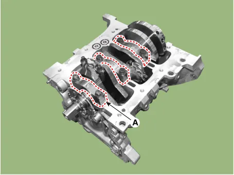
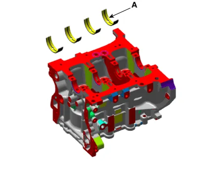
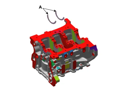
| 16. | Remove the main bearing caps (A).
|
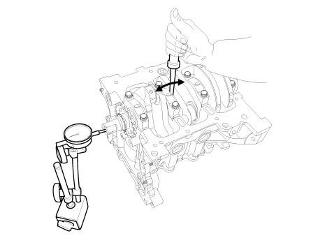
| 17. | Check the crankshaft end play. |
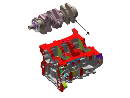
| 18. | Lift the crankshaft (A) out of engine, being careful not to damage journals.
|
|
| Inspection |
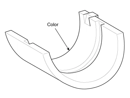
| 1. | Check the crankshaft main bearing oil clearance.
| |||||||||||||||||||||||||||||||||||||||||||||||||||||||||||||||||||||||||||||||||||||||||||||||||||||
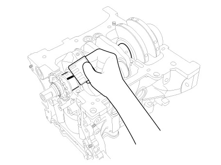

| 2. | Check crankshaft end play. Using a dial indicator, measure the thrust clearance while prying the crankshaft back and forth with a screwdriver.
If the end play is greater than maximum, replace the center bearings as a set.
|
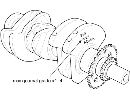
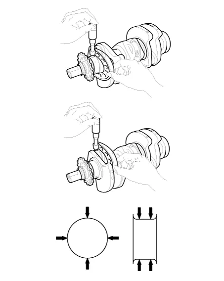
| 3. | Inspect the crankshaft main journals and pin journals. Using a micrometer, measure the diameter of each main journal and pin journal.
|
| Reassembly |
|
| 1. | Install the crankshaft main bearings.
|
| 2. | Place the crankshaft (A) on the cylinder block.
|
| 3. | Install the main bearing cap (A).
|

| 4. | Check the crankshaft end play. |
| 5. | Assemble the remaining parts in the reverse order of disassembly. |
In
case the crankshaft is replaced with a new one, select the proper
connecting rod bearing according to the pin journal mark on the
crankshaft.
|
Repair procedures Disassembly • Use fender covers to avoid damaging painted surfaces.• To avoid damaging the cylinder head, wait until the engine coolant temperature drops below normal temperature (20°C [68°F]) before removing it.
Repair procedures Disassembly • Use fender covers to avoid damaging painted surfaces.• To avoid damaging the cylinder head, wait until the engine coolant temperature drops below normal temperature (20°C [68°F]) before removing it.
Other information:
Kia Picanto (JA) 2017-2026 Service & Repair Manual: Start/Stop Button
Components and components location Component Repair procedures Removal 1.Disconnect the negative (-) battery terminal. 2.Remove the crash pad lower panel. (Refer to Body - "Crash Pad Lower Panel") 3.Remove the steering column shroud lower panel.
Kia Picanto (JA) 2017-2026 Service & Repair Manual: Immobilizer System
Schematic diagrams Circuit Diaram Description and operation Description The immobilizer system will disable the vehicle unless the proper ignition key is used, in addition to the currently available anti-theft systems such as car alarms, the immobilizer system aims to drastically reduce the rate of auto theft.
Categories
- Manuals Home
- Kia Picanto Owners Manual
- Kia Picanto Service Manual
- Heating,Ventilation, Air Conditioning
- Front Disc Brake
- Normal Condition
- New on site
- Most important about car
