Kia Picanto (JA): AVN System / AVN(Audio Video Navigation) head unit
Kia Picanto (JA) 2017-2026 Service & Repair Manual / Body Electrical System / AVN System / AVN(Audio Video Navigation) head unit
Components and components location
| Components |
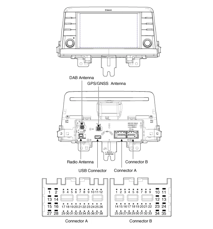
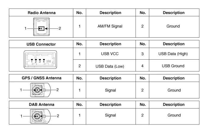
Connector Pin Information
|
No.
|
Connector A
|
Connector B
|
| 1 | Rear door left speaker (+) | - |
| 2 | Rear door left speaker (-) | MIC (+) |
| 3 | - | - |
| 4 | - | - |
| 5 | - | Antenna power |
| 6 | Camera power | Illumination (+) |
| 7 | Camera video | Non E-Call type : - E-Call type : Multmedia-CAN (High) |
| 8 | - | - |
| 9 | - | ALT Left_output (-) |
| 10 | AUX Audio_right input | Battery (+) |
| 11 | AUX Detect | Battery (+) |
| 12 | Steering wheel remote controller | Ground |
| 13 | Front door left speaker (+) | Ground |
| 14 | Front door left speaker (-) | - |
| 15 | Front door right speaker (-) | MIC (-) |
| 16 | Front door right speaker (+) | - |
| 17 | - | - |
| 18 | - | - |
| 19 | - | Default : Ground Option : Illumination (-) |
| 20 | Camera power_Ground | Non E-Call type : - E-Call type : Multmedia-CAN (Low) |
| 21 | Camera video_Ground | - |
| 22 | - | ACC |
| 23 | - | - |
| 24 | AUX Audio_left input | - |
| 25 | AUX Audio_Ground | Reverse |
| 26 | Steering wheel remote controller (Ground) | Door open |
| 27 | Rear door right speaker (-) | Door unlock status |
| 28 | Rear door right speaker (+) | Parking brake |
| 29 | - | 'P' Position |
| 30 | - | Auto light |
| 31 | - | - |
| 32 | - | - |
| 33 | Camera shield_Ground | IGN1 |
| 34 | - | - |
| 35 | - | - |
| 36 | - | |
| 37 | - | |
| 38 | Vehicle speed |
Repair procedures
| Removal |
|

| 1. | Disconnect the negative (-) battery terminal. |
| 2. | Remove the center fascia panel.
(Refer to Body - "Center Fascia Panel")
|
| 3. | Remove the AVN head unit (A) after loosening the mounting screws and nut.
|
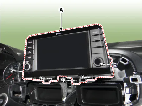
| 4. | Remove the AVN head unit after disconnecting the connectors and antenna cable (A).
|

| Installation |
| 1. | Install the AVN head unit after connecting the AVN head unit connectors and cable. |
| 2. | Install the center fascia panel. |
| 3. | Connect the negative (-) battery terminal. |
|

Components and components location Component Location 1 . AVN head unit 2. Roof antenna (Radio+GPS/GNSS+DAB+GSM) 3. Multimedia jack 4 . Steering wheel remote control (SWRC) 5 .
Repair procedures Inspection Troubleshooting of the speakers When handling the speakers :• Do not cause shock to the speakers by dropping or throwing them.
Other information:
Kia Picanto (JA) 2017-2026 Service & Repair Manual: Headlamps
Description and operation Description BI-FUNCTION 1. Definition – A headlamp with integrated functions of high and low beam – The light is controlled by rotating the shield inserted to the lens.
Kia Picanto (JA) 2017-2026 Service & Repair Manual: Sunroof
C
Categories
- Manuals Home
- Kia Picanto Owners Manual
- Kia Picanto Service Manual
- Normal Condition
- Thermostat
- Charging System
- New on site
- Most important about car

Copyright © 2026 www.kpicanto.com - 0.0299