Kia Picanto (JA): Rear Glass Defogger / Rear Glass Defogger Switch
Repair procedures
| Inspection |
| 1. | In the body electrical system, failure can be quickly diagnosed by using the vehicle diagnostic system (KDS/GDS). The diagnostic system (KDS/GDS) provides the following information.
|
| 2. | Select the 'Car model' and the 'Body Control Module (BCM)' to be checked in order to check the vehicle with the tester. |
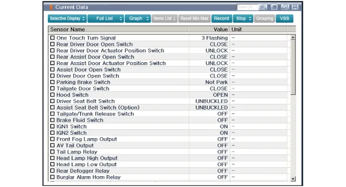
| 3. | Select the 'Current Data' menu to search the current state of the input/output data.
|
| 4. | To forcibly actuate the input value of the module to be checked, select option 'Actuation Test'
|

| Removal |
| 1. | Disconnect the negative (-) battery terminal. |
| 2. | Remove the heater and A/C controll unit.
(Refer to Heating, Ventilation, Air conditioning - "Heater & A/C Control Unit (Manual)")
(Refer to Heating, Ventilation, Air conditioning - "Heater & A/C Control Unit (Full Automatic)")
|
| Installation |
| 1. | Install the heater and A/C control unit. |
| 2. | Connect the negative (-) battery terminal. |
Repair procedures Inspection • Wrap tin foil around the end of the voltmeter test lead to prevent damaging the heater line.
Specifications Specification Item Specification Ultrasonic sensor Voltage rating DC 12V Detecting range 11.
Other information:
Kia Picanto (JA) 2017-2026 Service & Repair Manual: Emergency Call (eCall) Button
Components and components location Component Repair procedures Removal 1. Disconnect the negative (-) battery terminal. 2. Using a screwdriver or remover, separate the map lamp lens (A) from the map lamp. 3. Remove the map lamp (A) after loosening the screws.
Kia Picanto (JA) 2017-2026 Service & Repair Manual: Map Lamp
Repair procedures Removal • Put on gloves to prevent hand injuries. • When removing with a flat-tip screwdriver or remover, wrap protective tape around the tools to prevent damage to components.
Categories
- Manuals Home
- Kia Picanto Owners Manual
- Kia Picanto Service Manual
- Brake System
- Heating,Ventilation, Air Conditioning
- Body Electrical System
- New on site
- Most important about car
