Kia Picanto (JA): Cooling System / Cooling Fan
Components and components location
| Components |

| 1. Cooling fan 3. Cooling fan motor | 3. Cooling fan shroud |
Specifications
| Specifications |
|
Item
|
Specification
|
| Fan type | Puller |
| Fan speed control | ON - OFF |
| Air flow rate [㎥/h] | 1,570 - 8% min. |
| Fan speed (rpm) | 1,960 ± 8% |
| Current (A) | 10.0 + 10% max. |
Description and operation
| Description |
Schematic diagrams
| Circuit Diagram |

Repair procedures
| Removal and Installation |
| 1. | Remove the radiator.
(Refer to Cooling System - "Radiator")
|
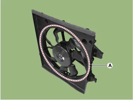
| 2. | Remove the cooling fan assembly (A) from the radiator.
|

| 3. | Install in the reverse order of removal. |
| Disassembly |
| 1. | Remove the cooling fan (A) from the cooling fan assembly.
|
| 2. | Remove the fan motor (A) from the cooling fan shroud.
|


| 3. | Assemble in the reverse order of disassembly. |
| Inspection |
| 1. | Disconnect the fan motor connector. |
| 2. | Connect the battery voltage to the "+" terminal and ground to "-" terminal. |
| 3. | Check the cooling fan motor operates well. |
Components and components location Components 1. Reservoir tank 2. Reservoir hose & pipe 3. Turbo charger water drain hose 4. Water return hose Repair procedures Removal and Installation 1.
Components and components location Components 1. Radiator 2. Radiator upper hose 3. Radiator lower hose 4. Radiator upper mounting bracket 5.
Other information:
Kia Picanto (JA) 2017-2026 Service & Repair Manual: Start/Stop Button
Components and components location Component Repair procedures Removal 1.Disconnect the negative (-) battery terminal. 2.Remove the crash pad lower panel. (Refer to Body - "Crash Pad Lower Panel") 3.Remove the steering column shroud lower panel.
Kia Picanto (JA) 2017-2026 Service & Repair Manual: Junction Box (Passenger Compartment)
Components and components location Component Location I/P Junction Box Circuit (I/P Junction Box) Description and operation Description Communication Network Diagram Abbreviation Explanation ABS Anti-lock Brake System ACU Airbag Control Un
Categories
- Manuals Home
- Kia Picanto Owners Manual
- Kia Picanto Service Manual
- Engine Oil and Filter
- Automatic Transaxle Fluid
- To set cruise control speed
- New on site
- Most important about car
