Kia Picanto (JA): Cooling System / Radiator
Components and components location
| Components |
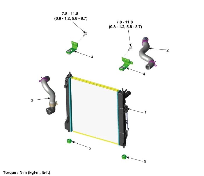
| 1. Radiator 2. Radiator upper hose 3. Radiator lower hose | 4. Radiator upper mounting bracket 5. Radiator lower mounting insulator |
Repair procedures
| Removal and Installation |
| 1. | Disconnect the battery negative terminal. |
| 2. | Remove the engine room under cover.
(Refer to Engine and Transaxle Assembly - "Engine Room Under Cover")
|
| 3. | Drain the coolant.
(Refer to Cooling System - "Coolant")
|
| 4. | Remove the air duct.
(Refer to Intake and Exhaust System - "Air Cleaner")
|
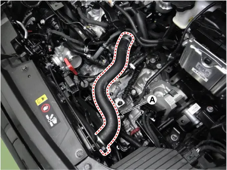
| 5. | Disconnect the radiator upper hose (A).
|
| 6. | Disconnect the radiator lower hose (A).
|

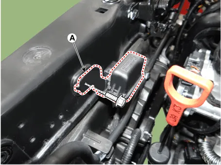
| 7. | Disconnect the cooling fan connector (A).
|

| 8. | Disconnect the ATF cooler hose (A).
|

| 9. | Remover the front bumper assembly.
(Refer to Body (Interior and Exterior) - "Front Bumper Assembly")
|
| 10. | Remove the headlamps.
(Refer to Body Electrical System - "Head Lamps")
|
| 11. | Disconnect the hood latch.
(Refer to Body (Interior and Exterior) - "Hood latch Assembly")
|
| 12. | Remove the multi-purpose check connector (MPCC) bracket (A).
|
| 13. | Disconnect the reservoir hose clip (A).
|

| 14. | Remove the radiator upper mounting bracket (A).
|

| 15. | Remove the radiator support upper member assembly (A).
|

| 16. | Disconnect the radiator reservoir hose (A).
|

| 17. | Remove the air guard (A).
[RH]
[LH]
|


| 18. | Separate the condenser and then remove the radiator (A).
|

| 19. | Remove the cooling fan assembly.
(Refer to Cooling System - "Cooling Fan")
|
| 20. | Install in the reverse order of removal. |
| 21. | Fill with engine coolant.
(Refer to Cooling System - "Coolant")
|
| 22. | Start engine and check for leaks. |
| 23. | Recheck engine coolant level. |
| Inspection |
| 1. | Install the pressure cap and pressure tester on a SST (0K253-G5100).
|
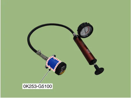
| 2. | Apply a pressure of 79.4 - 122.58 kPa (0.95 - 1.25 kgf/cm², 11.5 - 17.78 psi). |
| 3. | Check for a drop in pressure. |
| 4. | If the pressure drops, replace the pressure cap. |
| 1. | Wait
until engine is cool, then carefully remove the pressure cap and fill
the reservoir tank with engine coolant, then install it on the pressure
tester.
|

| 2. | Apply a pressure tester to the radiator and apply a pressure of 93.16 - 122.58 kPa (0.95 - 1.25 kgf/cm², 13.51 - 17.78 psi). |
| 3. | Inspect for engine coolant leaks and a drop in pressure. |
| 4. | Remove the tester and reinstall the pressure cap.
|

Components and components location Components 1. Cooling fan 3. Cooling fan motor 3. Cooling fan shroud Specifications Specifications Item Specification Fan type Puller Fan speed control ON - OFF Air flow rate [㎥/h] 1,570 - 8% min.
Repair procedures Removal and Installation 1.Disconnect the negative battery terminal. 2.Remove the engine room under cover and RH side cover. (Refer to Engine and Transaxle Assembly - “Engine Room Under Cover”) 3.
Other information:
Kia Picanto (JA) 2017-2026 Service & Repair Manual: Lighting System
Specifications Specification Item Type Bulb Watt (W) Front Headlamp Halogen (Position lamp) Low/High H4 LL 55/60 Turn signal lamp PY21WLL 21 Position lamp W5WLL 5 Halogen (Position lamp + DRL) Low/High HB3 (9005HL+) 60 Turn signal lamp LED LED Po
Kia Picanto (JA) 2017-2026 Service & Repair Manual: Smart Key Unit
Components and components location Components Connector Pin Information No. Connector A Connector B Connector C 1 - IGN2 Relay_output Battery (+)_Signal 2 SSB Switch1 signal_input P-CAN (Low) - 3 Driver door o
Categories
- Manuals Home
- Kia Picanto Owners Manual
- Kia Picanto Service Manual
- Cooling System
- Timing Chain
- Thermostat
- New on site
- Most important about car
