Kia Picanto (JA): Engine Mechanical System / Cylinder Head Assembly
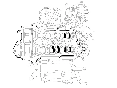
Components and components location
| Components |
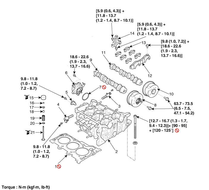
| 1. Cylinder head gasket 2. Cylinder head 3. Intake oil control valve (OCV) 4. Exhaust oil control valve (OCV) 5. Exhaust camshaft position sensor (CMPS) 6. Vacuum pump 7. Vacuum pump O-ring | 8. Exhaust CVVT assembly 9. Exhaust camshaft 10. Intake CVVT assembly 11. Intake camshaft 12. Camshaft front bearing cap 13. Camshaft middle bearing cap 14. Camshaft rear bearing cap | 15. Mechanical lash adjuster (MLA) 16. Retainer lock 17. Retainer 18. Valve stem seal 19. Valve spring 20. Valve spring seat 21. Valve |
Repair procedures
| Valve Clearance Inspection And Adjustment |
Inspect
and adjust the valve clearance when the engine is cold (Engine coolant
temperature : 20°C (68°F)) and cylinder head is installed on the
cylinder block. |

| 1. | Remove the cylinder head cover.
(Refer to Cylinder Head Assembly - “Cylinder Head Cover”)
|
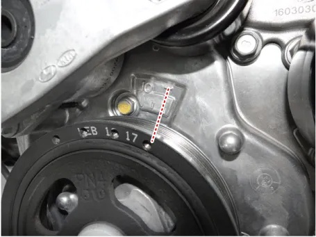
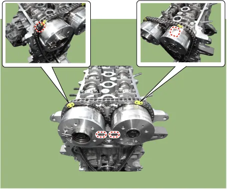
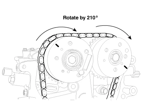
| 2. | Set No.1 cylinder to TDC/compression.
|
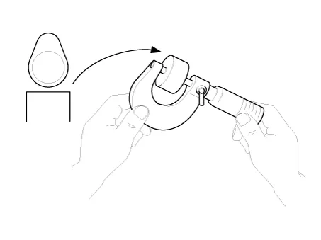
| 3. | Inspect the valve clearance.
|

| 4. | Adjust the intake and exhaust valve clearance.
|
Repair procedures Disassembly • Use fender covers to avoid damaging painted surfaces.• To avoid damaging the cylinder head, wait until the engine coolant temperature drops below normal temperature (20°C [68°F]) before removing it.
Components and components location Components 1. Oil filler cap 2. Cylinder head cover 3. Cylinder head cover gasket Repair procedures Removal • Use fender covers to avoid damaging painted surfaces.
Other information:
Kia Picanto (JA) 2017-2026 Service & Repair Manual: Front Fog Lamps
Repair procedures Removal 1.Disconnect the negative (-) battery terminal. 2.Remove the front bumper assembly. (Refer to Body - "Front Bumper Assembly") 3.Remove the front fog lamp assembly (A) after loosening the mounting screws.
Kia Picanto (JA) 2017-2026 Service & Repair Manual: Sunroof Motor
Repair procedures Inspection 1.Disconnect the negative (-) battery terminal. 2.Remove the roof trim assembly. (Refer to Body - "Roof Trim Assembly") 3.Remove the glass motor (A) after loosening the mounting screws. 4.
Categories
- Manuals Home
- Kia Picanto Owners Manual
- Kia Picanto Service Manual
- Thermostat
- Body Electrical System
- Charging System
- New on site
- Most important about car
