Kia Picanto (JA): Clutch System / Clutch Pedal
Components and components location
| Components |

| 1. Clutch pedal assembly | 2. Clutch cable |

| 1. Clutch pedal assembly 2. Ignition lock and clutch switch 3. Master cylinder | 4. Clutch regulator 5. Clutch tube |
Repair procedures
| Replacement |
| 1. | Turn ignition switch OFF and disconnect the negative (-) battery cable. |
| 2. | Loosen the clutch cable adjust nut (A) and then separate the clutch cable
|

| 3. | Remove the crash pad lower panel.
(Refer to Body - "Crash Pad Lower Panel")
|
| 4. | Remove the junction box.
(Refer to Body Electrical System - "Junction Box (Passenger Compartment))
|
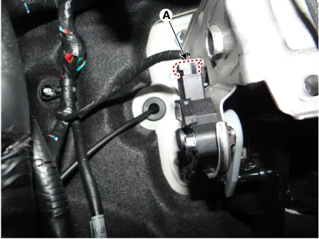
| 5. | Disconnect the cluch switch & ignition lock swtich connector (A).
|
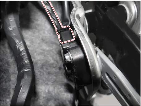
| 6. | Pushing the clutch pedal and then remove the clutch cable (A).
|

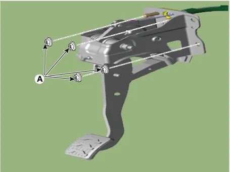
| 7. | Loosen the nuts (A) and then remove the clutch pedal.
|
| 8. | Install in the reverse order of removal. |
| 1. | Turn ignition switch OFF and disconnect the negative (-) battery cable. |
| 2. | Remove the crash pad lower panel.
(Refer to Body - "Crash Pad Lower Panel")
|
| 3. | Remove the junction box.
(Refer to Body Electrical System - "Junction Box (Passenger Compartment))
|
| 4. | Disconnect the ignition lock & clutch switch connector.
|
| 5. | Remove the push rod end (A) from the clutch pedal.
|
| 6. | Remove the battery.
G 1.0 T-GDI KAPPA (Refer to Engine Electrical System - "Battery")
|
| 7. | Remove the ECM.
G 1.0 T-GDI KAPPA (Refer to Engine Control / Fuel System - Engine Control Module (ECM)")
|
| 8. | Disconnect the reservoir hose (A) and clutch tube (B) from the clutch master cylinder after removeing the pin (C).
|

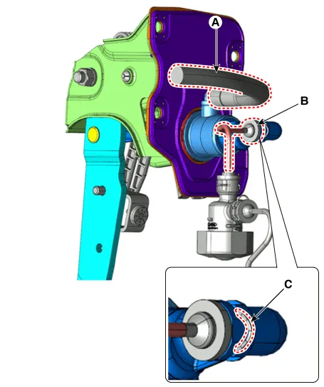
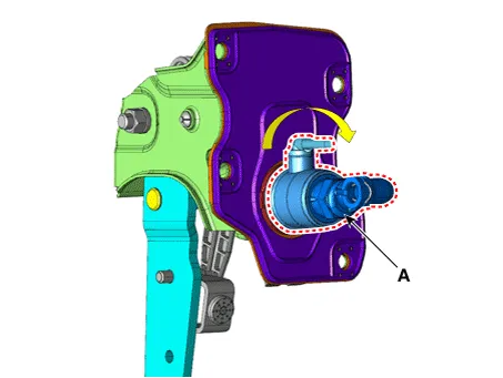
| 9. | Remove the clutch master cylinder (A) by turning it clockwise.
|
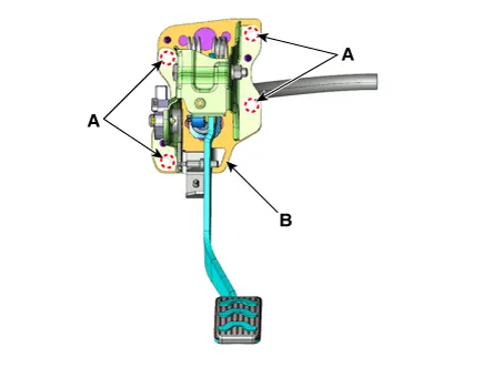
| 10. | Remove the clutch pedal (B) after loosening the mounting nuts (A).
|
| 11. | Install in the reverse order of removal. |
Specifications Specifications Item Specifications Working voltage DC 12.5V Operating force Initial position : 0.
Components and components location Components [Kappa 1.0 MPI / FFV, Kappa 1.2 MPI] 1. Clutch pedal assembly 2. Clutch cable Repair procedures Removal 1.
Other information:
Kia Picanto (JA) 2017-2026 Service & Repair Manual: Headlamp Leveling Switch
Schematic diagrams Circuit Diagram Repair procedures Removal 1.Disconnect the negative (-) battery terminal. 2.Remove the crash pad lower panel. (Refer to Body - "Crash Pad Lower Panel") 3.Remove the crash pad side switch (A) after loosening the mounting screws.
Kia Picanto (JA) 2017-2026 Service & Repair Manual: Heater & A/C Control Unit(Manual)
Components and components location Components [NON ISG] Connector pin function No. Connector A Connector B 1 Low Battery 2 Common Illumination (+) 3 Ground HTD 4 Middle (Low) ISG Battery 5 Middle (High) - 6 High Detent out (-) 7 - 8 Sen
Categories
- Manuals Home
- Kia Picanto Owners Manual
- Kia Picanto Service Manual
- Normal Condition
- Heating,Ventilation, Air Conditioning
- Fuel Delivery System
- New on site
- Most important about car
