Kia Picanto (JA): Clutch System / Clutch Switch
Specifications
| Specifications |
|
Item
|
Specifications
|
| Working voltage | DC 12.5V |
| Operating force | Initial position : 0.25 ± 0.15 N (0.025 ± 0.015 kg, 0.056 ± 0.034 lb) |
| Full position : 0.8 ± 0.2 N (0.08 ± 0.02 kgf, 0.579 ± 0.014 lb-ft) | |
| Working temperature | -40°C to 80°C (-40°F to 176°F) |
Description and operation
| Description |
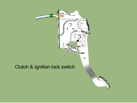
| – | Ignition lock switch is mounted on the clutch pedal. |
| – | Ignition lock switch is operated when you press the clutch pedal. |
| – | If the clutch pedal is not pressed down, the engine is not started. |
Repair procedures
| Inspection |
| 1. | Remove the clutch & ignition lock switch. |
| 2. | Rotate the switch lever to the direction of the arrow to check the operating point (A).
|


| Removal |
| 1. | Turn ignition switch OFF and disconnect the negative (-) battery cable. |
| 2. | Remove the crash pad lower panel.
(Refer to Body - "Crash Pad Lower Panel")
|
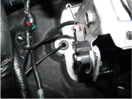
| 3. | Disconnect the cluch switch & ignition lock swtich connector (A).
|
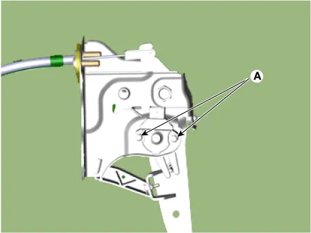
| 4. | Loosen the bolts (A) and then remove the ignition lock switch & clutch switch.
|
| Installation |
| 1. | Install in the reverse order of removal.
|


Specifications Specifications Item Specifications Working voltage DC 12.5V Operating force Initial position : 0.
Components and components location Components [Kappa 1.0 MPI / FFV, Kappa 1.2 MPI] 1. Clutch pedal assembly 2. Clutch cable [Kappa 1.0 T-GDI] 1.
Other information:
Kia Picanto (JA) 2017-2026 Service & Repair Manual: Rear Wiper Motor
Repair procedures Inspection Rear Wiper Motor 1.Remove the connector from the rear wiper motor. 2.Connect positive (+) battery cables to terminal 1 and negative (-) battery cables to terminal 2 respectively. 3.Check that the motor operates normally.
Kia Picanto (JA) 2017-2026 Service & Repair Manual: Seat Heater Switch
Components and components location Components 1. Driver side seat heater switch 2. Passenger side seat heater switch Schematic diagrams Circuit Diagram Repair procedures Removal 1. Disconnect the negative (-) battery terminal.
Categories
- Manuals Home
- Kia Picanto Owners Manual
- Kia Picanto Service Manual
- Charging System
- Battery
- Brake System
- New on site
- Most important about car
