
Kia Picanto (JA): AVN System / AVN Antenna
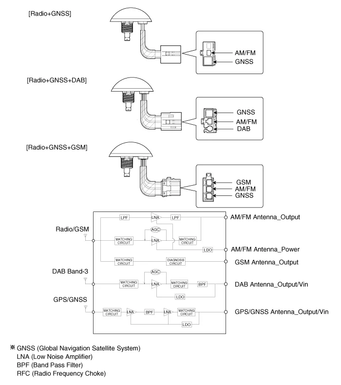
Components and components location
| Components |
| [Roof Antenna (Radio+GPS/GNSS+DAB+GSM)] |

Repair procedures
| Removal |
| 1. | Disconnect the negative (-) battery terminal. |
| 2. | Remove the roof trim assembly.
(Refer to Body - "Roof Trim Assembly")
|
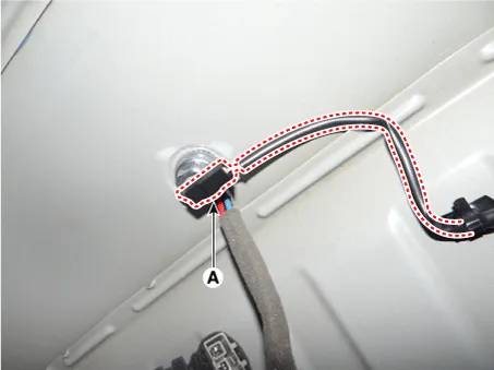
| 3. | Disconnect the radio antenna connector (A).
|

| 4. | Disconnect the roof antenna power connector (A).
|
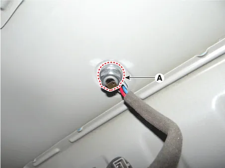
| 5. | Remove the roof antenna (B) after loosening a nut (A).
|

| Installation |
| 1. | Install the roof antenna. |
| 2. | Connect the radio antenna and roof antenna power connector. |
| 3. | Install the roof trim assembly. |
| 4. | Connect the negative (-) battery terminal.
|

Repair procedures Inspection Troubleshooting of the speakers When handling the speakers :• Do not cause shock to the speakers by dropping or throwing them.
Components and components location Components 1. Left Remote Control Switch (Audio + Hands free + Voice) 2. Right Remote Control Switch (Cruise+Trip Computer) Schematic diagrams Circuit Diagram [Audio] [Audio + Bluetooth] [Audio + Bluetooth + Voice] [Trip (2 Button) + SEG LCD Cluster] [Trip (2 Button) + ACC] [Trip (2 Button) + ACC + SLD] [Trip (4 Button) + DOT&TFT LCD Cluster] [Trip (4 Button) + ACC] [Trip (4 Button) + ACC + SLD] Repair procedures Removal 1.
Other information:
Kia Picanto (JA) 2017-2026 Service & Repair Manual: Ignition Switch Assembly
Repair procedures Inspection 1.Disconnect the key warning switch connector (A) and ignition switch connector (B) from the steering column. 2.Check for continuity between the terminals. 3.If continuity is not specified, replace the switch.
Kia Picanto (JA) 2017-2026 Service & Repair Manual: Power Door Lock Module
Components and components location Components 1. Door lock/unlock knob cable 2. Door inside handle cable 3. Door latch assembly Repair procedures Inspection • When removing with a flat-tip screwdriver or remover, wrap protective tape around the tools to prevent damage to
Categories
- Manuals Home
- Kia Picanto Owners Manual
- Kia Picanto Service Manual
- Normal Condition
- Automatic Transaxle Fluid
- Engine Control / Fuel System
- New on site
- Most important about car
