Kia Picanto (JA): Audio / Audio Remote Control
Components and components location
| Components |
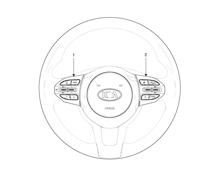
| 1. Left Remote Control Switch (Audio + Hands free + Voice) | 2. Right Remote Control Switch (Cruise+Trip Computer) |
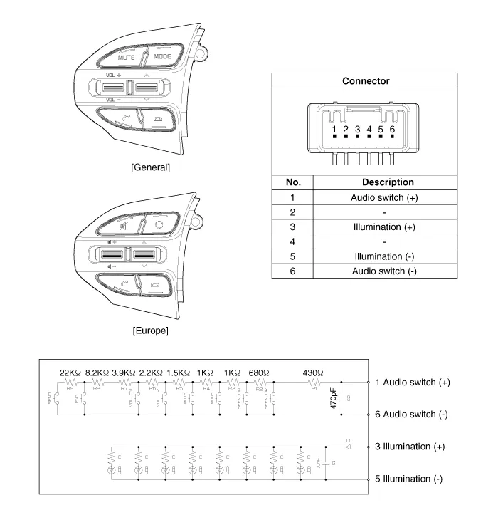
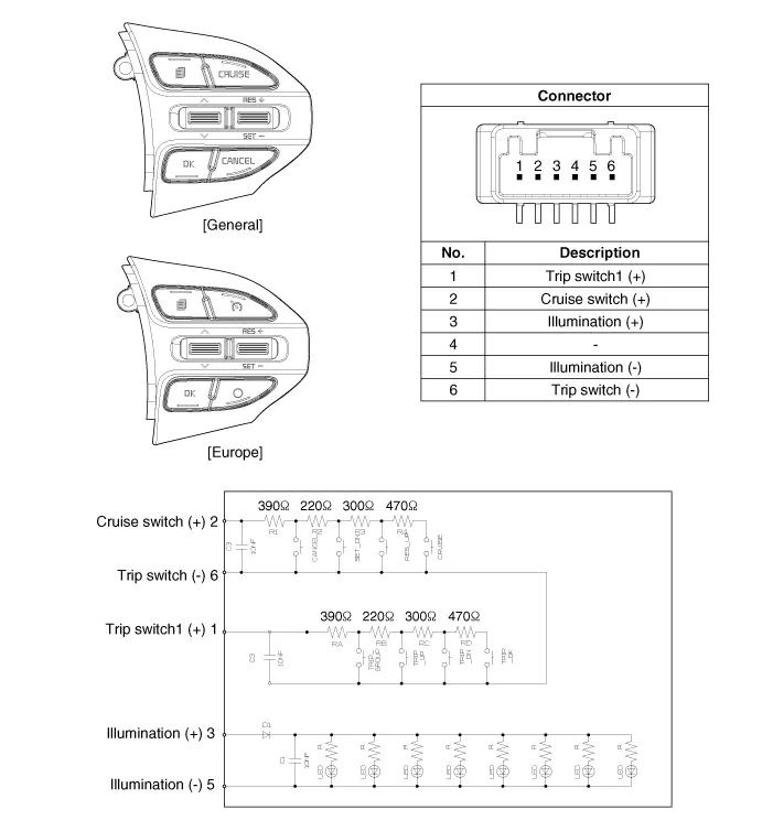
Schematic diagrams
| Circuit Diagram |

| [Audio] |

| [Audio + Bluetooth] |
| [Audio + Bluetooth + Voice] |

| [Trip (2 Button) + SEG LCD Cluster] |

| [Trip (2 Button) + ACC + Cruise] |

| [Trip (2 Button) + ACC + Cruise + SLD] |

| [Trip (4 Button) + DOT&TFT LCD Cluster] |

| [Trip (4 Button) + ACC + Cruise] |
| [Trip (4 Button) + ACC + Cruise + SLD] |

Repair procedures
| Removal |
| 1. | Disconnect the negative (-) battery terminal. |
| 2. | Remove the steering wheel assembly.
(Refer to Steering System - "Steering Wheel")
|
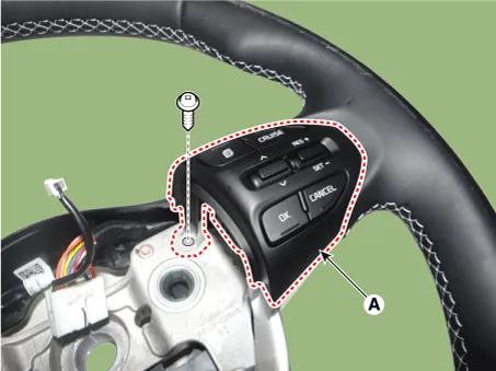
| 3. | Remove the steering wheel remote control (A) after loosening the mounting screws. [LH]
[RH]
|

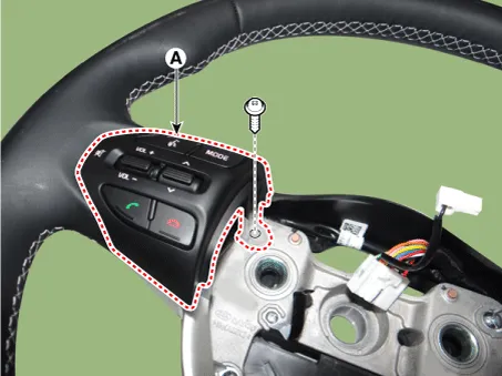

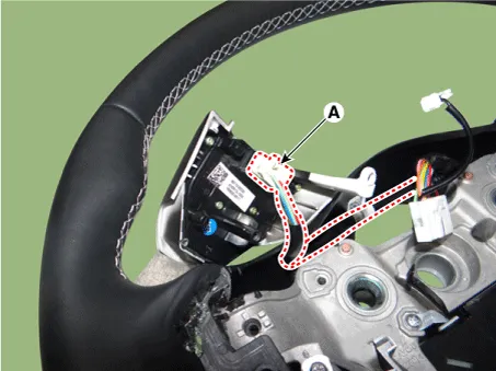
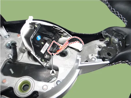
| 4. | Disconnect the steering wheel remote control connector (A). [LH]
[RH]
|
| Installation |
| 1. | Connect the steering wheel remote control connector. |
| 2. | Install the steering wheel remote control. |
| 3. | Install the steering wheel and driver airbag module. |
| 4. | Connect the negative (-) battery terminal. |
| Inspection |
| 1. | Check for resistance between terminals in each switch position (LH).
[LH : Audio + Hands free + Voice]
|

| 2. | Check for resistance between terminals in each switch position (RH).
[RH : Cruise + Trip]
|

Components and components location Components [Roof Antenna (Radio)] [Roof Antenna (Radio+GPS/GNSS+DAB+GSM)] Repair procedures Removal Roof antenna 1.
Schematic diagrams Circuit Diagram Description and operation Description The multimedia jack on the console upper cover is for customers who like to listen to external portable music players like the MP3 etc.
Other information:
Kia Picanto (JA) 2017-2026 Service & Repair Manual: Body Control Module (BCM)
Specifications Specifications [BCM Type] Items Specifications Rated voltage DC 12 V Operating voltage DC 9 - 16 V Operating temperature -31 - 167°F (-35 - 75°C) Dark current SMK : 3mA / Keyless : 3.
Kia Picanto (JA) 2017-2026 Service & Repair Manual: Headlamps
Description and operation Description BI-FUNCTION 1. Definition – A headlamp with integrated functions of high and low beam – The light is controlled by rotating the shield inserted to the lens.
Categories
- Manuals Home
- Kia Picanto Owners Manual
- Kia Picanto Service Manual
- Fuel Delivery System
- Front Disc Brake
- Engine Oil and Filter
- New on site
- Most important about car
