Kia Picanto (JA): Audio / Multimedia Jack
Schematic diagrams
| Circuit Diagram |

Description and operation
| Description |

Repair procedures
| Removal |
Put on gloves to protect your hands. |

|

| 1. | Disconnect the negative (-) battery terminal. |
| 2. | Using a screwdriver or remover, remove the floor console front bezel (A).
|

| 3. | Disconnect the connectors (A) from floor console front bezel.
|
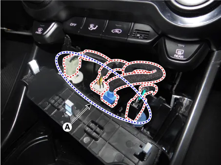
| 4. | Remove the multimedia jack (A) after releasing the fixed hooks.
|


| Installation |
| 1. | Install the multimedia jack. |
| 2. | Connect the connectors from the floor console front bezel. |
| 3. | Install the floor console front bezel. |
| 4. | Connect the negative (-) battery terminal.
|
Components and components location Components 1. Left Remote Control Switch (Audio + Hands free + Voice) 2. Right Remote Control Switch (Cruise+Trip Computer) Schematic diagrams Circuit Diagram [Audio] [Audio + Bluetooth] [Audio + Bluetooth + Voice] [Trip (2 Button) + SEG LCD Cluster] [Trip (2 Button) + ACC + Cruise] [Trip (2 Button) + ACC + Cruise + SLD] [Trip (4 Button) + DOT&TFT LCD Cluster] [Trip (4 Button) + ACC + Cruise] [Trip (4 Button) + ACC + Cruise + SLD] Repair procedures Removal 1.
Specifications Specifications Items Specifications Rated voltage 5V Load Max. 1mA (Relay load) Illuminations (LUX) 50 1.
Other information:
Kia Picanto (JA) 2017-2026 Service & Repair Manual: Power Window Motor
Components and components location Components [Standard Window Motor] [Safety Window Motor] Repair procedures Inspection • When removing with a flat-tip screwdriver or remover, wrap protective tape around the tools to prevent damage to components.
Kia Picanto (JA) 2017-2026 Service & Repair Manual: Rear Parking Assist System
Specifications Specification Item Specification Ultrasonic sensor Voltage rating DC 12V Detecting range 11.8 - 39.3 in (30 - 100 cm) Operation voltage DC 9 - 16 V Operation current 60mA Max.
Categories
- Manuals Home
- Kia Picanto Owners Manual
- Kia Picanto Service Manual
- Charging System
- Automatic Transaxle Fluid
- Cooling System
- New on site
- Most important about car
