
Kia Picanto (JA): Audio / Antenna
Components and components location
| Components |
| [Roof Antenna (Radio)] |

| [Roof Antenna (Radio+GPS/GNSS+DAB+GSM)] |


Repair procedures
| Removal |
| 1. | Disconnect the negative (-) battery terminal. |
| 2. | Remove the roof trim assembly.
(Refer to Body - "Roof Trim Assembly")
|
| 3. | Disconnect the radio antenna and power connector (A).
|
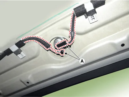
| 4. | Remove the roof antenna (B) after loosening a nut (A).
|


| Installation |
| 1. | Install the roof antenna. |
| 2. | Connect the radio antenna and roof antenna power connector. |
| 3. | Install the roof trim assembly. |
| 4. | Connect the negative (-) battery terminal.
|

| Inspection |
| 1. | Check for continuity between the center poles of antenna cable.
|
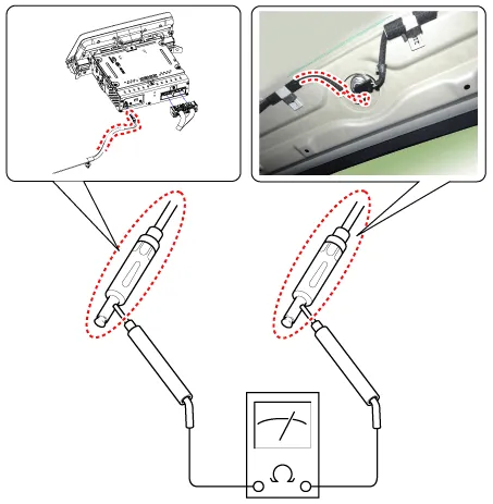
| 2. | Check for continuity between the outer poles of antenna cable. There should be continuity.
|

| 3. | If there is no continuity, replace the antenna cable. |
| 4. | Check for continuity between the center pole (A) and outer pole (B) of antenna cable. There should be no continuity.
|

| 5. | If there is continuity, replace the antenna cable. |
Repair procedures Inspection Troubleshooting of the speakers When handling the speakers :• Do not cause shock to the speakers by dropping or throwing them.
Components and components location Components 1. Left Remote Control Switch (Audio + Hands free + Voice) 2. Right Remote Control Switch (Cruise+Trip Computer) Schematic diagrams Circuit Diagram [Audio] [Audio + Bluetooth] [Audio + Bluetooth + Voice] [Trip (2 Button) + SEG LCD Cluster] [Trip (2 Button) + ACC + Cruise] [Trip (2 Button) + ACC + Cruise + SLD] [Trip (4 Button) + DOT&TFT LCD Cluster] [Trip (4 Button) + ACC + Cruise] [Trip (4 Button) + ACC + Cruise + SLD] Repair procedures Removal 1.
Other information:
Kia Picanto (JA) 2017-2026 Service & Repair Manual: Power Door Mirror Actuator
Components and components location Components 1. Side repeater lamp Repair procedures Inspection 1. Disconnect the negative (-) battery terminal. 2. Remove the front door quadrant inner cover (A). 3. Disconnect the tweeter speaker connector (A).
Kia Picanto (JA) 2017-2026 Service & Repair Manual: Parking Assist Sensor
Components and components location Components Repair procedures Removal 1.Disconnect the negative (-) battery terminal. 2.Remove the rear bumper assembly. (Refer to Body - "Rear Bumper Assembly") 3.Disconnect the connector (A) from the ultrasonic sensor.
Categories
- Manuals Home
- Kia Picanto Owners Manual
- Kia Picanto Service Manual
- Charging System
- Heating,Ventilation, Air Conditioning
- Suspension System
- New on site
- Most important about car
