Kia Picanto (JA): Brake System / Stop Lamp Switch
Components and components location
| Components |
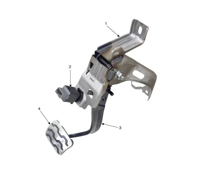
| 1. Brake member assembly 2. Stop lamp switch | 3. Brake pedal arm assembly 4. Brake pedal pad |
Schematic diagrams
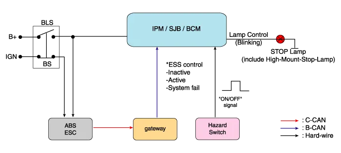
| Schematic Diagram |
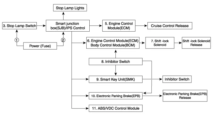
| System circuit diagram |
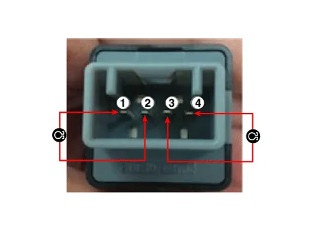
| Terminal function |

|
Terminal
|
Description
|
| 1 | IGN1 |
| 2 | Engine Control Module (ECM) |
| 3 | B+ |
| 4 | Stop Lamp |
Troubleshooting
| Troubleshooting |
| 1. | Part diagnosis
|
| 2. | Symptom diagnosis
|
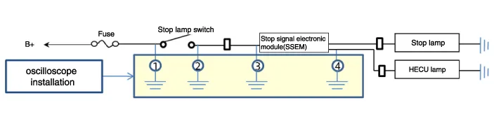
| 3. | Stop lamp switch system diagnosis
SSEM : Stop Signal Electronic Module |
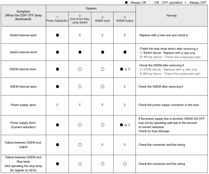
| 4. | Refer to DTC guide when the related DTC codes are displayed. |
Repair procedures
| Removal |
| 1. | Switch "OFF" ignition and disconnect the negative (-) battery terminal. |
| 2. | Remove the crash pad lower panel.
(Refer to Body - "Crash Pad Lower Panel")
|
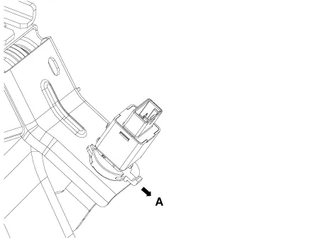
| 3. | Disconnect the stop lamp switch connector (A).
|

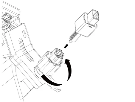
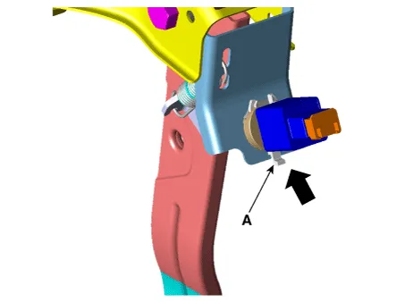
| 4. | Pull the locking plate (A) as indicated by the
|
| 5. | Turn brake switch 45° counterclockwise and remove it.
|
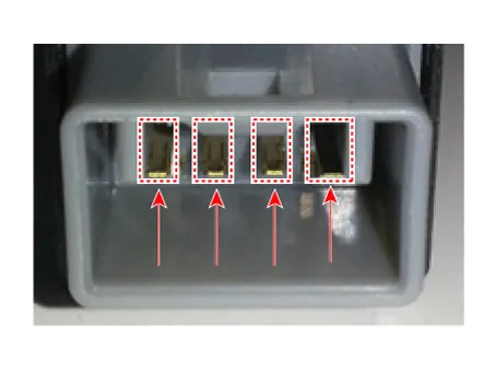
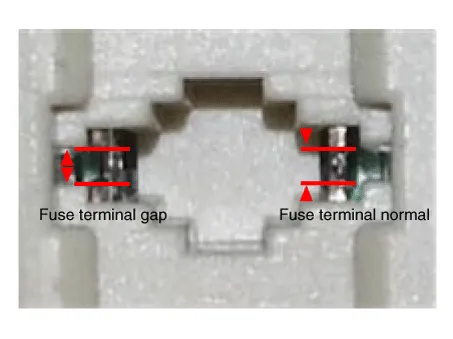
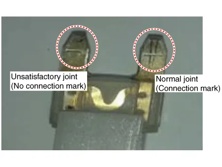
| 6. | Inspect the removed stop lamp switch according to the below procedures.
|
| Installation |
| 1. | Fix the brake pedal arm and insert the brake switch fully until the contact part is invisible.
|

| 2. | After inserting, turn the brake switch 45° clockwise, and then assemble locking plate by pushing it.
|
| 3. | Check the gap (A) between brake switch and bracket.
|


| 4. | Install the brake switch connector (A).
|
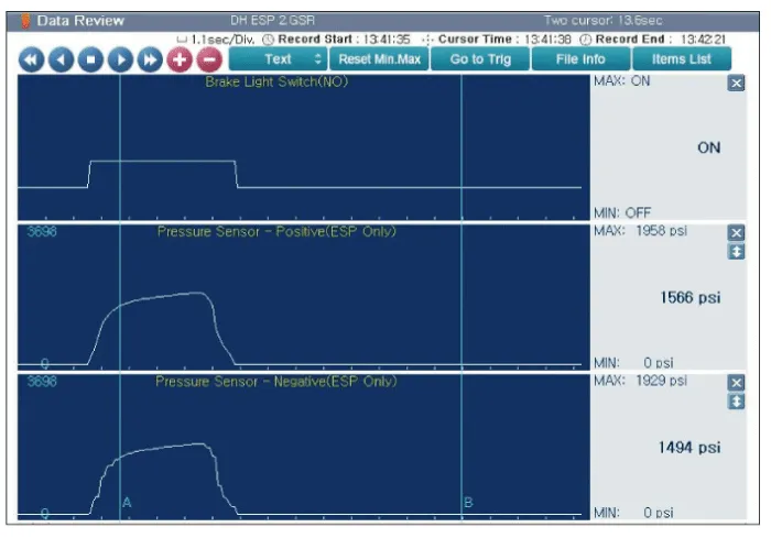
| Inspection |
| 1. | Analyze GDS data and confirm if there is anything wrong with the stop lamp switch.
|


Components and components location Components 1. Shoe hold down pin 2. Shoe adjuster 3. Upper return spring 4. Adjusting lever 5. Shoe 6. Adjusting spring 7.
Components and components location Components 1. Parking brake lever 2. Equalizer assembly 3. Rear parking brake cable Repair procedures Removal The parking brake cables must not be bent or distorted.
Other information:
Kia Picanto (JA) 2017-2026 Service & Repair Manual: High Mounted Stop Lamp
Repair procedures Removal 1. Disconnect the negative (-) battery terminal. 2. Open the tailgate. 3. Loosen the high mounted stop lamp mounting nuts (A). 4. Disconnect the washer nozzle (A) and high mounted stop lamp connector (B). 5. Remove the high mounted stop lamp (C).
Kia Picanto (JA) 2017-2026 Service & Repair Manual: Rear Washer Motor
Repair procedures Inspection 1.With the washer motor connected to the reservoir tank, fill the reservoir tank with water. Before filling the reservoir tank with water, check the filter for foreign material or contamination.
Categories
- Manuals Home
- Kia Picanto Owners Manual
- Kia Picanto Service Manual
- Cylinder Head
- Engine Mechanical System
- Brake System
- New on site
- Most important about car
