Kia Picanto (JA): Brake System / Parking Brake System
Components and components location
| Components |

| 1. Parking brake lever 2. Equalizer assembly | 3. Rear parking brake cable |
Repair procedures
| Removal |
The parking brake cables must not be bent or distorted. This will lead to stiff operation and premature failure. |

| 1. | Remove the floor console.
(Refer to body - "Floor console assembly")
|
| 2. | Disconnect the connector (A) of parking brake switch.
|
| 3. | Loosen the adjusting nut (A) and the parking brake cables.
|

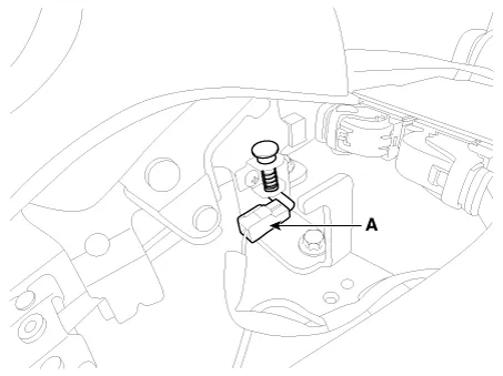
| 4. | Remove the parking brake lever assembly (A) after removing the bolts.
|
| 5. | Raise the vehicle, and make sure it is securely supported. |
| 6. | Remove the rear tire and wheel. |
| 7. | Remove the parking brake cable from the brake shoe. [Drum brake only]
(Refer to Brake System - "Rear Drum Brake")
|
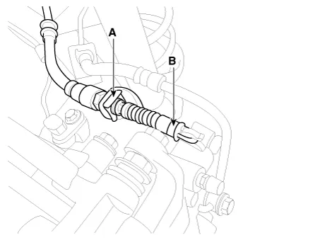
| 8. | Remove the parking brake cable (B), after removing the clip (A). [Disc Brake Type]
[Drum Brake Type]
|

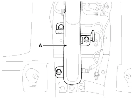
| 9. | Loosen the parking brake cable bracket bolts and remove the parking brake cable (A). |
| Installation |
| 1. | Install the parking brake cable (A). |
| 2. | Install the parking brake cable (B), after install the clip (A). [Disc Brake Type]
[Drum Brake Type]
|
| 3. | Install the brake shoe. [Drum brake only]
(Refer to Brake System - "Rear Drum Brake")
|
| 4. | Install the rear tire and wheel. |
| 5. | Install the parking brake lever assembly (A).
|
| 6. | Install the parking brake cable (B) and cable retainer (A).
|
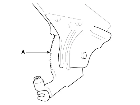
| 7. | Apply a coating of the specified grease to each sliding parts (A) of the ratchet plate or the ratchet pawl.
|
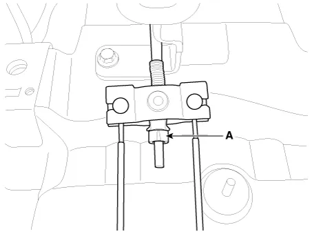
| 8. | Install the parking brake cable adjuster, then adjust the parking brake lever stroke by turning adjusting nut (A).
|
| 9. | Release
the parking brake lever fully, and check that parking brakes do not
drag when the rear wheels are turned. Readjust if necessary. |
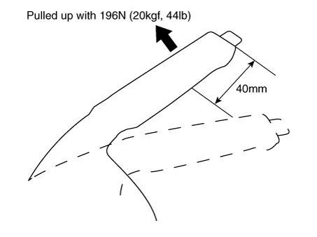
| 10. | Make sure that the parking brakes are fully applied when the parking brake lever is pulled up fully. |
| 11. | Reconnect the connector (A) of parking brake switch.
|
| 12. | Install the floor console.
(Refer to body - "Floor console assembly")
|
| Adjustment |
| Parking Brake Lever Stroke Adjustment |
| 1. | Remove the floor console.
(Refer to body - "Floor console assembly")
|
| 2. | Apply a coating of the specified grease to each sliding parts (A) of the ratchet plate or the ratchet pawl.
|
| 3. | Install the parking brake cable adjuster, then adjust the parking brake lever stroke by turning adjusting nut (A).
|
| 4. | Release
the parking brake lever fully, and check that parking brakes do not
drag when the rear wheels are turned. Readjust if necessary. |
| 5. | Make sure that the parking brakes are fully applied when the parking brake lever is pulled up fully. |
| 6. | Install the floor console.
(Refer to body - "Floor console assembly")
|
| Parking Brake Shoe Clearance Adjustment |
| 1. | Depress the brake pedal several times to set the self-adjusting brake.
|
Components and components location Components 1. Brake member assembly 2. Stop lamp switch 3. Brake pedal arm assembly 4. Brake pedal pad Schematic diagrams Schematic Diagram System circuit diagram Terminal function Terminal Description 1 IGN1 2 Engine Control Module (ECM) 3 B+ 4 Stop Lamp Troubleshooting Troubleshooting 1.
Components and components location Components 1. ABS control module (HECU) 2. Front wheel speed sensor 3. Rear wheel speed sensor Description and operation Description This specification applies to HCU(Hydraulic Control Unit) and ECU(Electronic Control Unit) of the HECU.
Other information:
Kia Picanto (JA) 2017-2026 Service & Repair Manual: Headlamp Leveling Actuator
Components and components location Components Repair procedures Removal 1.Disconnect the negative (-) battery terminal. 2.Remove the headlamp assembly. (Refer to Lighting System - "Headlamps") Installation 1.Install the headlamp assembly.
Kia Picanto (JA) 2017-2026 Service & Repair Manual: Rear Glass Defogger Printed Heater
Repair procedures Inspection • Wrap tin foil around the end of the voltmeter test lead to prevent damaging the heater line. Apply pressure on the tin foil with hand and move the tin foil along the grid line to check for open circuits.
Categories
- Manuals Home
- Kia Picanto Owners Manual
- Kia Picanto Service Manual
- Charging System
- Suspension System
- Front Disc Brake
- New on site
- Most important about car
