
Kia Picanto (JA): Crash Pad / Steering Column Shroud Panel
Components and components location
| Component Location |
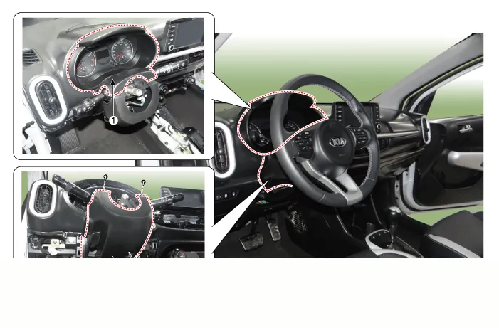
| 1. Steering column shroud upper panel | 2. Steering column shroud lower panel |
Repair procedures
| Replacement |
Put on gloves to protect your hands. |

|

| 1. | Remove the steering column shroud upper panel (A) by using a remover.
|

| 2. | Install in the reverse order of removal.
|
| 1. | Remove the Steering column shroud upper panel. |
| 2. | Remove the crash pad side cover [LH] (A) by using a remover.
|

| 3. | Remove the hood latch release handle (A) by using a remover.
|

| 4. | Remove the front door scuff trim (A) by using a remover.
|

| 5. | Remove the cowl side trim (A) by using a remover.
|
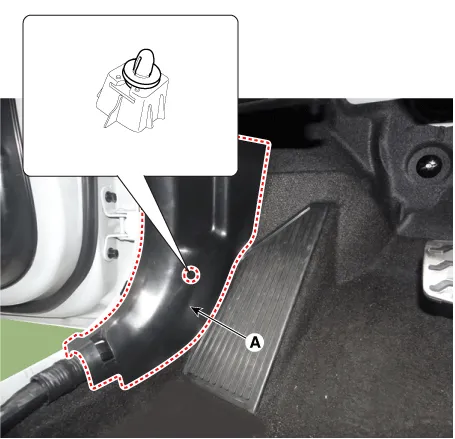
| 6. | Remove the passenger compartment junction box cover (A).
|

| 7. | Separate the crash pad lower panel (A) after loosening the bolts and screws.
|
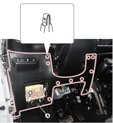
| 8. | Disconnect the crash pad lower side switch connector (A).
|
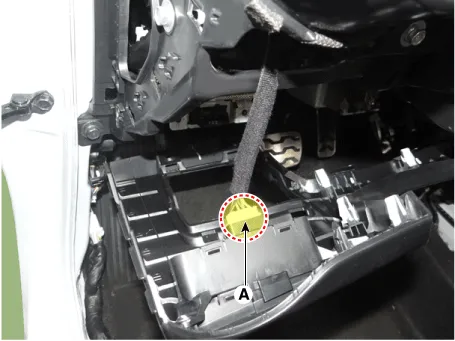
| 9. | Remove the steering column shroud lower panel (A) after loosening the mounting screws.
|

| 10. | Install in the reverse order of removal.
|
Components and components location Component Location 1. Glove box housing assembly Repair procedures Replacement Put on gloves to protect your hands.
Components and components location Component Location 1. Crash pad center lower panel Repair procedures Replacement Put on gloves to protect your hands.
Other information:
Kia Picanto (JA) 2017-2026 Service & Repair Manual: Power Door Locks
Components and components location Component Location 1. Driver power window switch 2. Assist power window switch 3 . Body Comtrol Module (BCM) 4 . Door lock knob 5 . Tailgate actuator 6. Door latch lock actuator 7 . Door lock/unlock switch 8 .
Kia Picanto (JA) 2017-2026 Service & Repair Manual: Rear Glass Defogger Switch
Repair procedures Inspection 1.In the body electrical system, failure can be quickly diagnosed by using the vehicle diagnostic system (KDS/GDS).The diagnostic system (KDS/GDS) provides the following information.(1)Self diagnosis : Checking failure and code number (DTC)(2) Current data : Checking the system input/output data state (3)Actuation
Categories
- Manuals Home
- Kia Picanto Owners Manual
- Kia Picanto Service Manual
- Suspension System
- Engine And Transaxle Assembly
- Cylinder Head
- New on site
- Most important about car
