Kia Picanto (JA): Brake System / Stop Lamp Switch
Components and components location
| Components |
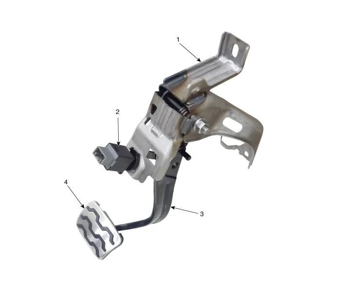
| 1. Brake member assembly 2. Stop lamp switch | 3. Brake pedal arm assembly 4. Brake pedal pad |
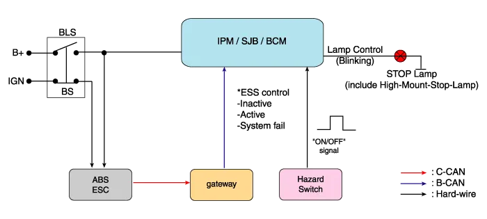
Schematic diagrams
| Schematic Diagram |
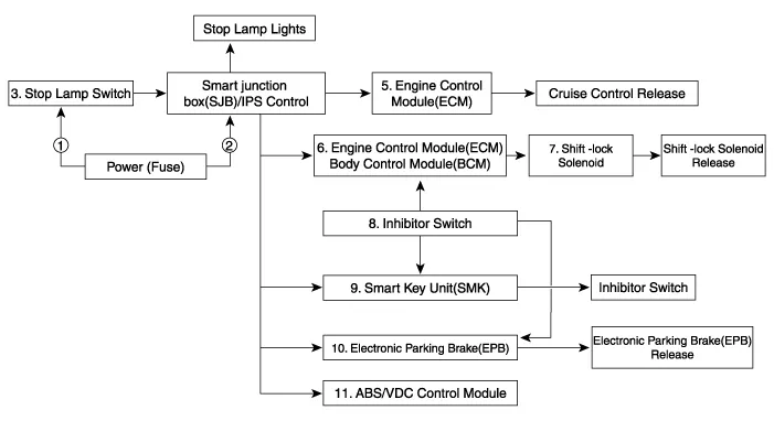
| System circuit diagram |
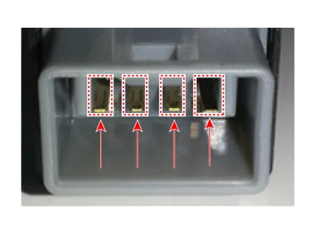
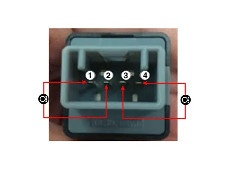
| Terminal function |

|
Terminal
|
Description
|
| 1 | IGN1 |
| 2 | Engine Control Module (ECM) |
| 3 | B+ |
| 4 | Stop Lamp |
Troubleshooting
| Troubleshooting |
| 1. | Part diagnosis
|
| 2. | Symptom diagnosis
|
| 3. | Stop lamp switch system diagnosis
SSEM : Stop Signal Electronic Module |
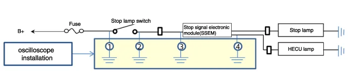
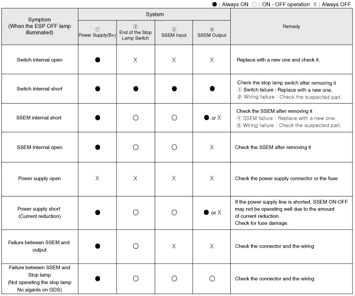
| 4. | Refer to DTC guide when the related DTC codes are displayed. |
Repair procedures
| Removal |
| 1. | Switch "OFF" ignition and disconnect the negative (-) battery terminal. |
| 2. | Remove the crash pad lower panel.
(Refer to Body - "Crash Pad Lower Panel")
|
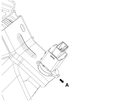
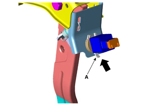
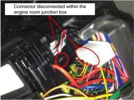
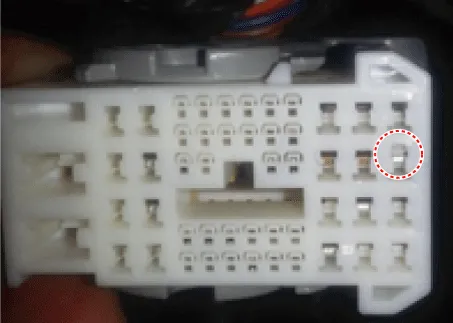
| 3. | Disconnect the stop lamp switch connector (A).
|

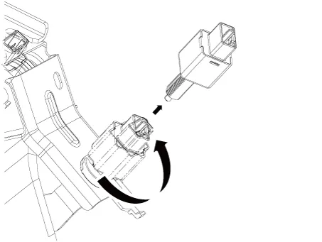
| 4. | Pull the locking plate (A) as indicated by the
|
| 5. | Turn brake switch 45° counterclockwise and remove it.
|
| 6. | Inspect the removed stop lamp switch according to the below procedures.
|
| Installation |
| 1. | Fix the brake pedal arm and insert the brake switch fully until the contact part is invisible.
|

| 2. | After inserting, turn the brake switch 45° clockwise, and then assemble locking plate by pushing it.
|
| 3. | Check the gap (A) between brake switch and bracket.
|


| 4. | Install the brake switch connector (A).
|
| Inspection |
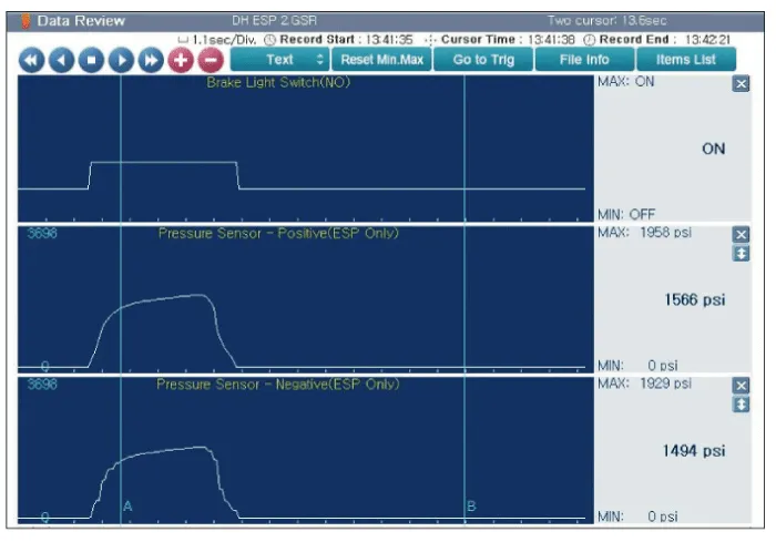
| 1. | Analyze GDS data and confirm if there is anything wrong with the stop lamp switch.
|


Components and components location Components 1. Shoe hold down pin 2. Shoe adjuster 3. Upper return spring 4. Adjusting lever 5. Shoe 6. Adjusting spring 7.
Components and components location Components 1. Parking brake lever 2. Equalizer assembly 3. Rear parking brake cable Repair procedures Removal The parking brake cables must not be bent or distorted.
Other information:
Kia Picanto (JA) 2017-2026 Service & Repair Manual: Body Control Module (BCM)
Specifications Specifications [BCM Type] Items Specifications Rated voltage DC 12 V Operating voltage DC 9 - 16 V Operating temperature -31 - 167°F (-35 - 75°C) Dark current SMK : 3mA / Keyless : 3.
Kia Picanto (JA) 2017-2026 Service & Repair Manual: Turn Signal Lamp
Repair procedures Removal Door Mirror Turn Signal Lamp 1. Disconnect the negative (-) battery terminal. 2. Remove the mirror (A) from the mirror holder. Be careful not to damage the fixing clips (A). 3. Disconnect the heating connectors (A) from the mirror.
Categories
- Manuals Home
- Kia Picanto Owners Manual
- Kia Picanto Service Manual
- Thermostat
- Cooling System
- Normal Condition
- New on site
- Most important about car
