Kia Picanto (JA): Power Door Locks / Power Door Lock Switch
Repair procedures
| Inspection |
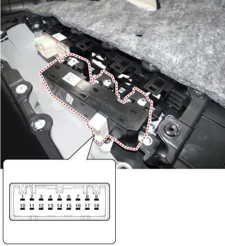
| 1. | Check for continuity between the terminals. If there is an abnormality, replace the switch.
|

| Removal |
|

| 1. | Disconnect the negative (-) battery terminal. |
| 2. | Remove the front left door trim.
(Refer to Body - "Front Door Trim")
|
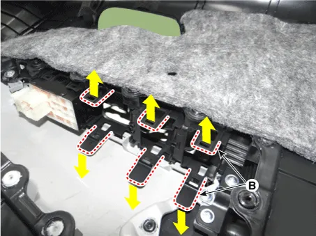
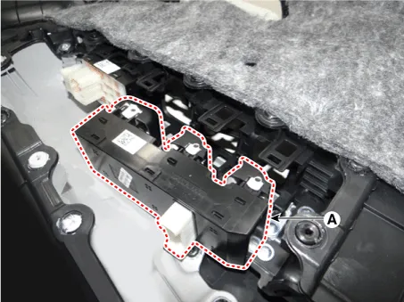
| 3. | Remove the power window switch assembly (A) by pulling out both ends of the switch holders (B).
|
| Installation |
| 1. | Install the driver power window switch. |
| 2. | Install the front door trim after connecting the connector. |
| 3. | Connect the negative (-) battery terminal. |
Components and components location Components 1. Door lock/unlock knob cable 2. Door inside handle cable 3. Door latch assembly Repair procedures Inspection • When removing with a flat-tip screwdriver or remover, wrap protective tape around the tools to prevent damage to components.
Components and components location Component Location 1. Power door mirror 2. Power door mirror switch 3. Power folding mirror switch
Other information:
Kia Picanto (JA) 2017-2026 Service & Repair Manual: Fuses And Relays
C
Kia Picanto (JA) 2017-2026 Service & Repair Manual: Temperature Control Actuator
Components and components location Component Location 1. Temerature Control Actuator Description and operation Description 1. Heater unit includes mode control actuator and temperature control actuator. 2. Temperature control actuator is located at the heater unit.
Categories
- Manuals Home
- Kia Picanto Owners Manual
- Kia Picanto Service Manual
- Coolant
- Brake System
- Fuel Delivery System
- New on site
- Most important about car
