Kia Picanto (JA): Features of your vehicle / Hood
Opening the hood

1. Pull the release lever to unlatch the hood. The hood should pop open slightly.
WARNING
Open the hood after turning off the engine on a flat surface, shifting the shift lever to the P(Park) position for automatic transaxle and to the 1st(First) gear or R(Reverse) for manual transaxle, and setting the parking brake.
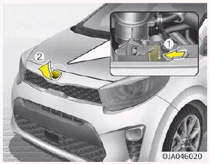
2. Go to the front of the vehicle, raise the hood slightly, push the secondary latch (1) inside of the hood center and lift the hood (2).

3. Pull the support rod from the hood.
4. Hold the hood open with the support rod.
WARNING
Hot parts
Grasp the support rod in the area wrapped in yellow cap.
The cap will help prevent you from being burned by hot metal when the engine is hot.
Hood open warning
The warning message (for Type B cluster) will appear on the LCD display when hood is open.
The warning chime will operate when the vehicle is being driven above 3 km/h (2 mph) with the hood open.
Closing the hood
1. Before closing the hood, check the following:
- All filler caps in engine compartment must be correctly installed.
- Gloves, rags or any other combustible material must be removed from the engine compartment.
2. Return the support rod to its clip to prevent it from rattling.
3. Lower the hood until it is about 30 cm above the closed position and let it drop. Make sure that it locks into place.
4. Check that the hood has engaged properly. If the hood can be raised slightly, it is not properly engaged. Open it again and close it with a little more force.
WARNING
- Before closing the hood, ensure that all obstructions are removed from the hood opening. Closing the hood with an obstruction present in the hood opening may result in property damage or severe personal injury.
- Do not leave gloves, rags or any other combustible material in the engine compartment. Doing so may cause a heat-induced fire.
WARNING
- Always double check to be sure that the hood is firmly latched before driving away. If it is not latched, the hood could fly open while the vehicle is being driven, causing a total loss of visibility, which might result in an accident.
- The support rod must be inserted completely into the hole provided in the hood whenever you inspect the engine compartment. This will prevent the hood from falling and possibly injuring you.
- Do not move the vehicle with the hood raised. The view will be blocked and the hood could fall or be damaged.
To raise or lower the window, turn the window regulator handle clockwise or counterclockwise. WARNING When opening or closing the windows, make sure your passenger's arms, hands and body are safely out of the way.
Opening the fuel filler lid The fuel-filler lid must be opened from inside the vehicle by pulling up on the fuel-filler lid opener located on the front floor area on the driver’s seat.
Other information:
Kia Picanto (JA) 2017-2026 Service & Repair Manual: Headlamp Leveling Actuator
Components and components location Components Repair procedures Removal 1.Disconnect the negative (-) battery terminal. 2.Remove the headlamp assembly. (Refer to Lighting System - "Headlamps") Installation 1.Install the headlamp assembly.
Kia Picanto (JA) 2017-2026 Service & Repair Manual: Rear Wiper/Washer
C
Categories
- Manuals Home
- Kia Picanto Owners Manual
- Kia Picanto Service Manual
- Brake System
- Engine Control / Fuel System
- Engine Oil and Filter
- New on site
- Most important about car
