
Kia Picanto (JA): Fuel Delivery System / Fuel Filter
Repair procedures
| Removal |
| 1. | Remove the fuel pump.
(Refer to Fuel Delivery System - "Fuel Pump")
|
| 2. | Disconnect the fuel pump motor connector (A) and fuel sender connector (B).
|
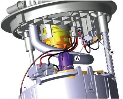
| 3. | Disconnect the fuel feed tube quick-connector (A) after removing the fixing clip (B).
|
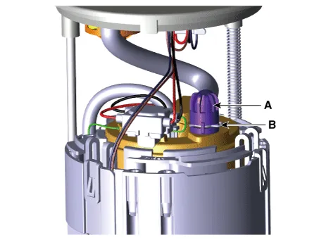
| 4. | Remove the cushion pipe fixing clip (A), and then separate the head assembly (B) from reservoir cup.
|
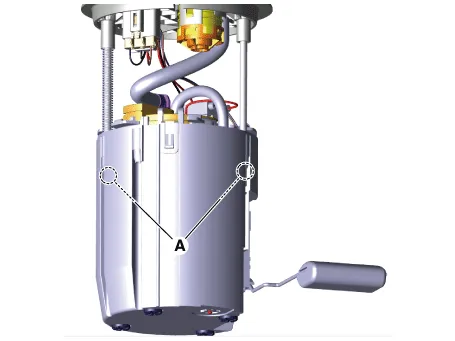
| 5. | Press the fixing hook (A) with a driver and then remove fuel sender in the arrow direction.
|
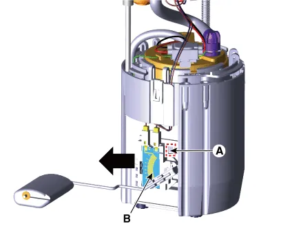
| 6. | Remove the reservoir-cup (B) after releasing the fixing hooks (A).
|
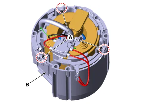
| 7. | Disconnect the ground pin (A).
|
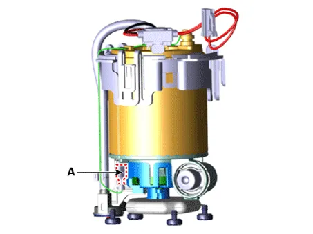
| 8. | Remove the fixing clip (A), and then assist pump assembly (B).
|

| 9. | Remove the free-filter (A) after releasing the fixing hooks.
|
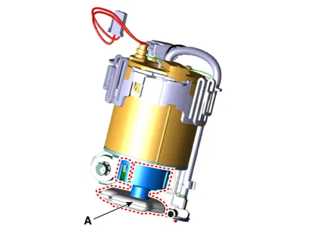
| 10. | Separate the electric pump motor (A).
|
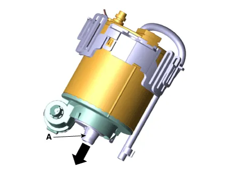
| 11. | Replace new fuel filter.
|
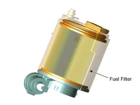
| Installation |
| 1. | Install in the reverse order of removal. |
Repair procedures Inspection [Fuel pump] 1.Turn ignition switch OFF and disconnect the negative (-)battery cable. 2.Remove the fuel pump assembly.
Repair procedures Removal 1.Remove the fuel pump. (Refer to Fuel Delivery System - "Fuel Pump") 2.Disconnect the fuel sender connector (A).
Other information:
Kia Picanto (JA) 2017-2026 Service & Repair Manual: Headlamp Leveling Switch
Schematic diagrams Circuit Diagram Repair procedures Removal 1.Disconnect the negative (-) battery terminal. 2.Remove the crash pad lower panel. (Refer to Body - "Crash Pad Lower Panel") 3.Remove the crash pad side switch (A) after loosening the mounting screws.
Kia Picanto (JA) 2017-2026 Service & Repair Manual: Evaporator Core
Repair procedures Replacement 1.Disconnect the negative (-) battery terminal. 2.Remove the heater unit. (Refer to Heater - "Heater Unit") 3.Remove the Evaporator temperature sensor. (Refer to Air Conditioning System - "Evaporator Temperature Sensor") 4.
Categories
- Manuals Home
- Kia Picanto Owners Manual
- Kia Picanto Service Manual
- Clutch Cable
- Charging System
- Normal Condition
- New on site
- Most important about car
