Kia Picanto (JA): Front Suspension System / Front Lower Arm
Repair procedures
| Removal |
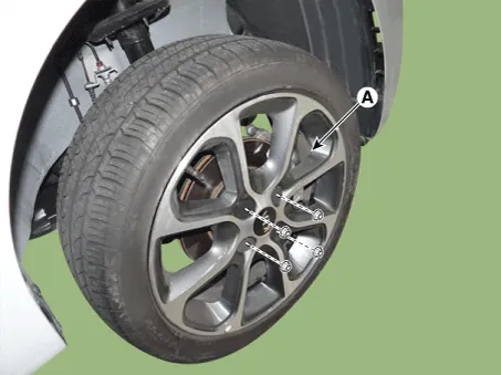
| 1. | Remove the front/rear wheel tire (A).
|

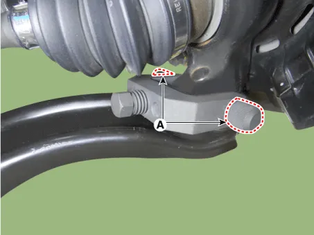
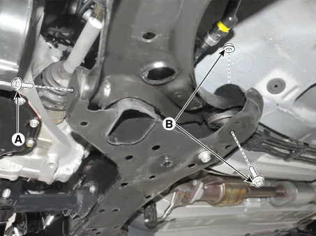
| 2. | Remove the lower arm bolt and nut.
|

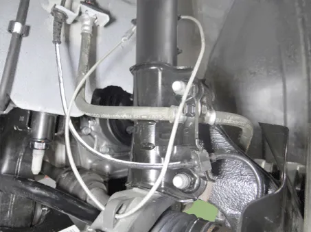
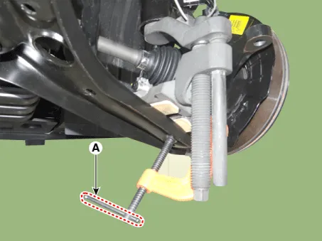
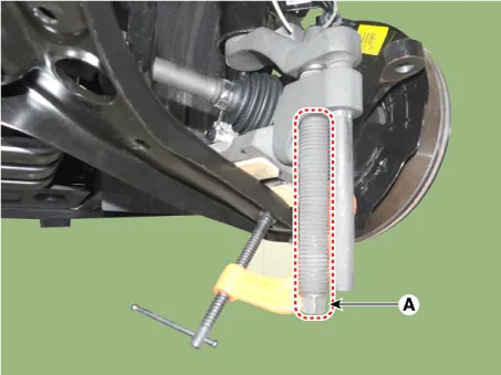
| 3. | Remove the front lower arm from the front knuckle using the SST (0K545-A9100).
|


| 4. | Remove the lower arm from the sub frame.
|
| 5. | Install in the reverse order of removal. |
| 6. | Check the wheel alignment.
(Refer to Tires/Wheels - "Alignment")
|
| 1. | Remove the front lower arm.
(Refer to Suspension System - "Front Lower Arm")
|
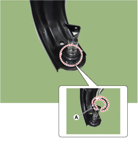
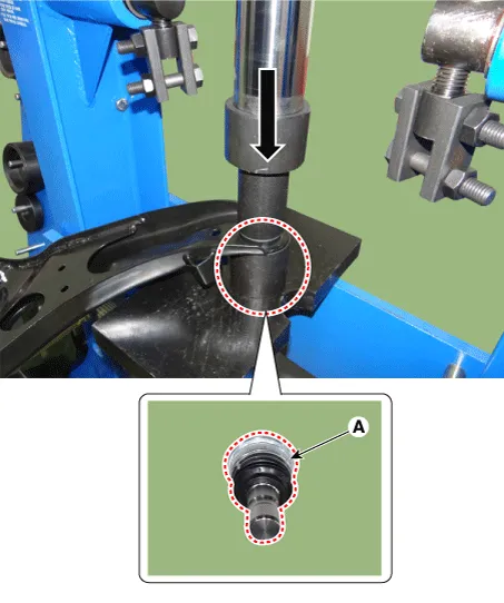
| 2. | Remove the snap ring (A) from the lower arm ball joint.
|
| 3. | Using a press, remove the ball joint (A) from the lower arm.
|
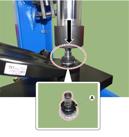
| 4. | Using a press, install the new ball joint.
|
| Inspection |
| 1. | Check the bushing for wear and deterioration. |
| 2. | Check the lower arm for bending or breakage. |
| 3. | Check the lower arm for deformation. |
| 4. | Check all bolts and nuts. |
Components and components location Components Location 1. Lock nut 2. Insulator dust cap 3. Self lock nut 4. Strut insulator 5. Strut bearing 6.
Repair procedures Removal 1.Remove the universal joint bolt (A). Tightening torque : 32.4 - 37.3 N·m (3.3 - 3.8 kgf·m, 23.9 - 27.
Other information:
Kia Picanto (JA) 2017-2026 Service & Repair Manual: Power Door Locks
Components and components location Component Location 1. Driver power window switch 2. Assist power window switch 3 . Body Comtrol Module (BCM) 4 . Door lock knob 5 . Tailgate actuator 6. Door latch lock actuator 7 . Door lock/unlock switch 8 .
Kia Picanto (JA) 2017-2026 Service & Repair Manual: Smart Key System
Specifications Specifications Smart Key Unit Items Specification Rated voltage DC 12 V Operating voltage DC 9 - 16 V Operating temperature -31 - 167°F (-35 - 75°C) Load Max. 4mA (When welcome light function "OFF") RF Receiver Items
Categories
- Manuals Home
- Kia Picanto Owners Manual
- Kia Picanto Service Manual
- Charging System
- To set cruise control speed
- Body Electrical System
- New on site
- Most important about car
