
Kia Picanto (JA): Floor Console / Floor Console Assembly
Kia Picanto (JA) 2017-2026 Service & Repair Manual / Body (Interior and Exterior) / Floor Console / Floor Console Assembly
Components and components location
| Component Location |

| 1. Floor console assembly |
Repair procedures
| Replacement |
Put on gloves to protect your hands. |

|

| 1. | To remove the gear knob & gear boots (A) pull both of it up.
|

| 2. | Separate the console upper cover (A) by using a remover.
|

| 3. | Remove the indicator cover, after disconnecting the connectors (A).
|
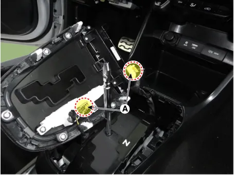
| 4. | Separate the console front tray (A).
|

| 5. | Remove the console front tray, after disconnecting the connectors (A).
|
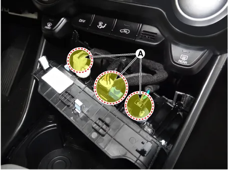
| 6. | Remove the parking brake cover (A).
|

| 7. | Remove the console armrest mat (A).
|

| 8. | Remove the console complete (A).
|

| 9. | Install in the reverse order of removal.
|
Components and components location Components [M/T] 1. Floor console assembly 2. Rear console tray mat 3. Parking brake cover 4. Floor console front bezel assembly 5.
Components and components location Component Location 1. Rear console cover Repair procedures Replacement Put on gloves to protect your hands.
Other information:
Kia Picanto (JA) 2017-2026 Service & Repair Manual: Fuses And Relays
C
Kia Picanto (JA) 2017-2026 Service & Repair Manual: Mode Control Actuator
Components and components location Component Location 1. Mode Control Actuator Description and operation Description The mode control actuator is located at the heater unit. It adjusts position of mode door by operating mode control actuator based on signal of A/C control unit.
Categories
- Manuals Home
- Kia Picanto Owners Manual
- Kia Picanto Service Manual
- Fuel Delivery System
- Cylinder Head
- Engine Control / Fuel System
- New on site
- Most important about car

Copyright © 2026 www.kpicanto.com - 0.0186