
Kia Picanto (JA): Engine And Transaxle Assembly / Engine Room Under Cover
Repair procedures
| Removal and Installation |
| 1. | Remove the engine room under cover (A).
|
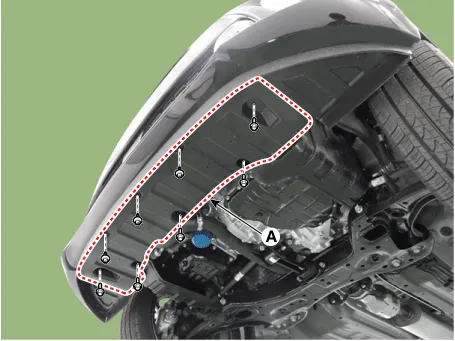
| 2. | Install in the reverse order of removal. |
| 1. | Remove the engine room side covers (A).
[LH]
[RH]
|


| 2. | Install in the reverse order of removal. |
Components and components location Components 1. Engine mounting bracket 2. Roll rod bracket 3. Transaxle mounting bracket Repair procedures Removal and Installation Engine Mounting Bracket 1.
Other information:
Kia Picanto (JA) 2017-2026 Service & Repair Manual: Emergency Call (eCall) Button
Components and components location Component Repair procedures Removal 1. Disconnect the negative (-) battery terminal. 2. Using a screwdriver or remover, separate the map lamp lens (A) from the map lamp. 3. Remove the map lamp (A) after loosening the screws.
Kia Picanto (JA) 2017-2026 Service & Repair Manual: Power Door Mirror Switch
Components and components location Component Schematic diagrams Circuit Diagram [Folding Mirror Type] [Non-Folding Mirror Type] Repair procedures Inspection 1.Check for continuity between the terminals in each switch position according to the table.
Categories
- Manuals Home
- Kia Picanto Owners Manual
- Kia Picanto Service Manual
- Suspension System
- Clutch Cable
- Heating,Ventilation, Air Conditioning
- New on site
- Most important about car
