Kia Picanto (JA): Engine And Transaxle Assembly / Engine Mounting
Components and components location
| Components |
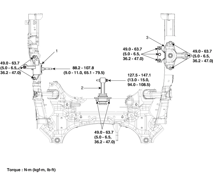
| 1. Engine mounting bracket 2. Roll rod bracket | 3. Transaxle mounting bracket |
Repair procedures
| Removal and Installation |
| 1. | Remove the engine room under cover and RH side cover.
(Refer to Engine and Transaxle Assembly - Engine Room Under Cover")
|
| 2. | Remove the reservoir tank.
(Refer to Cooling System - "Reservoir Tank")
|
| 3. | Install the jack to the edge of upper oil pan to support the engine.
|

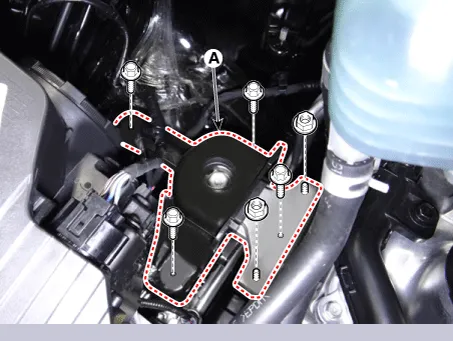
| 4. | Remove the engine mounting bracket (A).
|
| 5. | Install in the reverse order of removal. |
| 1. | Remove the engine room under cover.
(Refer to Engine and Transaxle Assembly - "Engine Room Under Cover")
|
| 2. | Remove the intercooler inlet hoses & pipe (A).
|
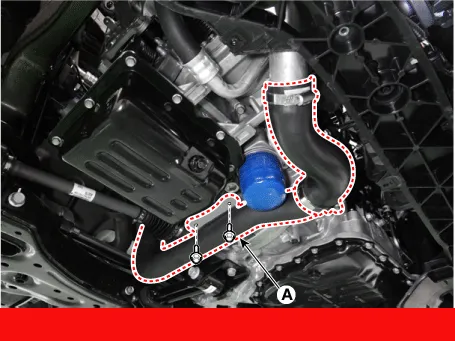
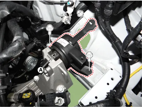
| 3. | Remove the roll rod bracket (A).
|
| 4. | Install in the reverse order of removal. |
| 1. | Remove the battery and tray.
(Refer to Engine Electrical System - "Battery")
|
| 2. | Remove the engine room under cover and LH side cover.
(Refer to Engine and Transaxle Assembly - Engine Room Under Cover")
|
| 3. | Install the jack to the edge of transaxle. |
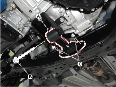
| 4. | Remove the transaxle side panel packing (A).
|

| 5. | Remove the transaxle mounting bolts (A).
|
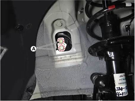
| 6. | Remove the transaxle mounting bracket (A).
|
| 7. | Install in the reverse order of removal. |
Repair procedures Removal and Installation Engine Room Under Cover 1. Remove the engine room under cover (A). Tightening torque : 7.
Repair procedures Removal • Use fender covers to avoid damaging painted surfaces. • To avoid damage, unplug the wiring connectors carefully while holding the connector portion.
Other information:
Kia Picanto (JA) 2017-2026 Service & Repair Manual: Rear Glass Defogger Printed Heater
Repair procedures Inspection • Wrap tin foil around the end of the voltmeter test lead to prevent damaging the heater line. Apply pressure on the tin foil with hand and move the tin foil along the grid line to check for open circuits.
Kia Picanto (JA) 2017-2026 Service & Repair Manual: Rear Parking Assist System
Specifications Specification Item Specification Ultrasonic sensor Voltage rating DC 12V Detecting range 11.8 - 39.3 in (30 - 100 cm) Operation voltage DC 9 - 16 V Operation current 60mA Max.
Categories
- Manuals Home
- Kia Picanto Owners Manual
- Kia Picanto Service Manual
- Charging System
- Heating,Ventilation, Air Conditioning
- Cylinder Head
- New on site
- Most important about car
