Kia Picanto (JA): Lighting System / Rear Combination Lamp
Repair procedures
| Removal |
| 1. | Disconnect the negative (-) battery terminal. |
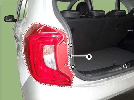
| 2. | Remove the rear combination lamp (A) after loosening the screws.
|
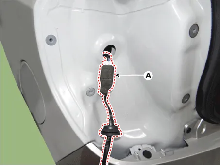
| 3. | Remove the rear combination lamp packing (A).
|

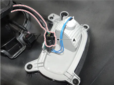
| 4. | Disconnect the rear combination lamp connector (A).
|
| 1. | Disconnect the negative (-) battery terminal. |
| 2. | Remove the rear bumper assembly.
(Refer to Body - "Rear bumper Assembly")
|
| 3. | Disconnect the back up lamp connector (A).
|
| 4. | Remove the back up lamp (A) after loosening the screws.
|

| Bulb Replacement |
| 1. | Remove the rear combination lamp. |
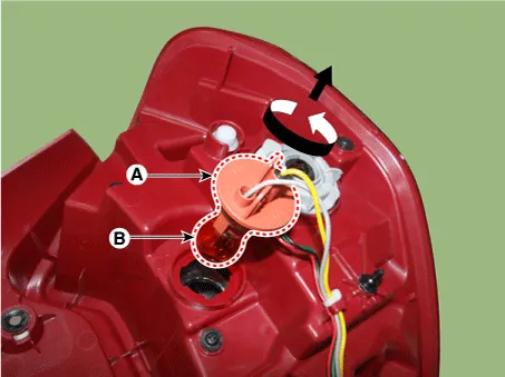
| 2. | Remove the turn signal lamp bulb (B) by turning the socket (A) counterclockwise.
|
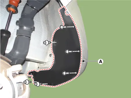
| 1. | Remove the rear tire. |
| 2. | Remove the rear wheel guard (A) after loosening the mounting screws and clips.
|
| 3. | Remove the back up lamp bulb (B) by turning the socket (A) counterclockwise.
|

| Installation |
| 1. | Connect the rear combination lamp connector. |
| 2. | Install the rear combination lamp. |
| 3. | Connect the negative (-) battery terminal. |
| 1. | Install the back up lamp. |
| 2. | Install the rear bumper assembly. |
| 3. | Connect the negative (-) battery terminal. |
Repair procedures Removal 1. Disconnect the negative (-) battery terminal. 2. Open the tailgate. 3. Loosen the high mounted stop lamp mounting nuts (A).
Specifications Specifications Items Specifications Rated voltage DC 12 V Operating temperature range -22 - 176°F (-30 - 80°C) Rated load Washer Washer : 6A (Motor load) Components and components location Component 1 .
Other information:
Kia Picanto (JA) 2017-2026 Service & Repair Manual: Rear Parking Assist System
Specifications Specification Item Specification Ultrasonic sensor Voltage rating DC 12V Detecting range 11.8 - 39.3 in (30 - 100 cm) Operation voltage DC 9 - 16 V Operation current 60mA Max.
Kia Picanto (JA) 2017-2026 Service & Repair Manual: Front Wiper Motor
Components and components location Component Location 1. Cap 2. Nut 3. Wiper arm & blade 4. Cowl top cover 5. Bolt 6. Wiper motor & linkage assembly 7. Wiper motor connector Repair procedures Removal 1.Disconnect the negative (-) battery terminal.
Categories
- Manuals Home
- Kia Picanto Owners Manual
- Kia Picanto Service Manual
- Thermostat
- Body Electrical System
- Coolant
- New on site
- Most important about car
