Kia Picanto (JA): Clutch System / Clutch Tube
Components and components location
| Components |

| 1. Clutch pedal assembly 2. Ignition lock and clutch switch 3. Master cylinder | 4. Clutch regulator 5. Clutch tube |
Repair procedures
| Removal |
| 1. | Turn ignition switch OFF and disconnect the negative (-) battery cable. |
| 2. | Remove the battery and battery tray.
G 1.0 T-GDI KAPPA (Refer to Engine Electrical System - "Battery")
|
| 3. | Remove the ECM.
G 1.0 T-GDI KAPPA (Refer to Engine Control / Fuel System - Engine Control Module (ECM)")
|
| 4. | Remove the engine room under cover.
G 1.0 T-GDI KAPPA (Refer to Engine Mechanical System - "Engine Room Under Cover")
|
| 5. | Loosen the clutch tube bracket bolts (B) and then remove the snap pin (A), from the regulator.
|
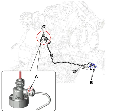
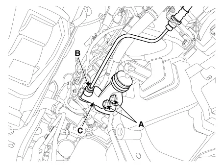
| 6. | Loosen the release cylinder bolts (A) and then clutch tube nut (B) after removing release cylinder assembly (C).
|
| Installation |
When installing, O-rings of clutch tube should be replaced with a new one. |

| 1. | Install in the reverse order of removal. |
| 2. | After be equipped, perform bleeding air procedure after pouring the brake fluid.
(Refer to Clutch Release Cylinder - "Adjustment")
|
Components and components location Components [Kappa 1.0 T-GDI] 1. Clutch pedal assembly 2. Ignition lock and clutch switch 3. Master cylinder 4.
Repair procedures Removal [Kappa 1.0 T-GDI] 1.Remove the engine room under cover. G 1.0 T-GDI KAPPA (Refer to Engine Mechanical System - "Engine Room Under Cover") 2.
Other information:
Kia Picanto (JA) 2017-2026 Service & Repair Manual: Power Door Locks
Components and components location Component Location 1. Driver power window switch 2. Assist power window switch 3 . Body Comtrol Module (BCM) 4 . Door lock knob 5 . Tailgate actuator 6. Door latch lock actuator 7 . Door lock/unlock switch 8 .
Kia Picanto (JA) 2017-2026 Service & Repair Manual: Smart Key System
Specifications Specifications Smart Key Unit Items Specification Rated voltage DC 12 V Operating voltage DC 9 - 16 V Operating temperature -31 - 167°F (-35 - 75°C) Load Max. 4mA (When welcome light function "OFF") RF Receiver Items
Categories
- Manuals Home
- Kia Picanto Owners Manual
- Kia Picanto Service Manual
- Body Electrical System
- Cylinder Head
- Thermostat
- New on site
- Most important about car
