Kia Picanto (JA): Clutch System / Regulator
Components and components location
| Components |
[Kappa 1.0 T-GDI]

| 1. Clutch pedal assembly 2. Ignition lock and clutch switch 3. Master cylinder | 4. Clutch regulator 5. Clutch tube |
Repair procedures
| Removal |
| 1. | Turn ignition switch OFF and disconnect the negative (-) battery cable |
| 2. | Remove the battery.
G 1.0 T-GDI KAPPA (Refer to Engine Electrical System - "Battery")
|
| 3. | Remove the ECM.
G 1.0 T-GDI KAPPA (Refer to Engine Control / Fuel System - Engine Control Module (ECM)")
|
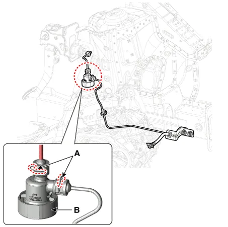
| 4. | Remove the snap pins (A) and then remove the regulator (B).
|
| Installation |
| 1. | Install in the reverse order of removal. |
| 2. | After be equipped, perform bleeding air procedure in clutch release cylinder after pouring the brake fluid.
(Refer to Clutch Release Cylinder - "Adjustment")
|
Components and components location Components [Kappa 1.0 T-GDI] 1. Clutch pedal assembly 2. Ignition lock and clutch switch 3. Master cylinder 4.
Components and components location Components [Kappa 1.0 T-GDI] 1. Clutch pedal assembly 2. Ignition lock and clutch switch 3. Master cylinder 4.
Other information:
Kia Picanto (JA) 2017-2026 Service & Repair Manual: Rear Parking Assist System
Specifications Specification Item Specification Ultrasonic sensor Voltage rating DC 12V Detecting range 11.8 - 39.3 in (30 - 100 cm) Operation voltage DC 9 - 16 V Operation current 60mA Max.
Kia Picanto (JA) 2017-2026 Service & Repair Manual: Sunroof
C
Categories
- Manuals Home
- Kia Picanto Owners Manual
- Kia Picanto Service Manual
- Battery
- Cooling System
- Brake System
- New on site
- Most important about car

Copyright © 2026 www.kpicanto.com - 0.0234