Kia Picanto (JA): Clutch System / Clutch Master Cylinder
Components and components location
| Components |

| 1. Clutch pedal assembly 2. Ignition lock and clutch switch 3. Master cylinder | 4. Clutch regulator 5. Clutch tube |
Repair procedures
| Removal |
| 1. | Turn ignition switch OFF and disconnect the negative (-) battery cable. |
| 2. | Remove the crash pad lower panel.
(Refer to Body - "Crash Pad Lower Panel")
|
| 3. | Disconnect the ignition lock & clutch switch connector.
|
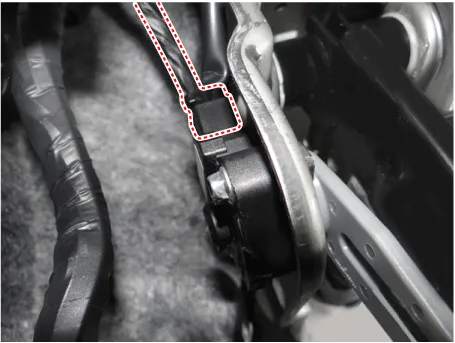
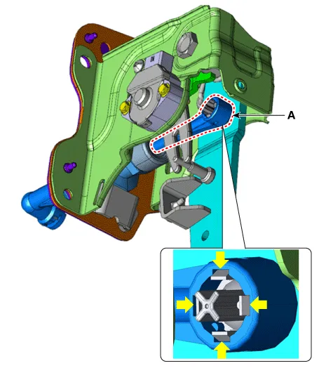
| 4. | Remove the push rod end (A) from the clutch pedal.
|
| 5. | Remove the battery.
G 1.0 T-GDI KAPPA (Refer to Engine Electrical System - "Battery")
|
| 6. | Remove the ECM.
G 1.0 T-GDI KAPPA (Refer to Engine Control / Fuel System - Engine Control Module (ECM)")
|
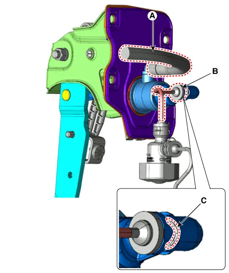
| 7. | Disconnect the reservoir hose (A) and clutch tube (B) from the clutch master cylinder after removeing the pin (C).
|

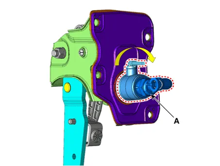
| 8. | Remove the clutch master cylinder (A) by turning it clockwise.
|
| Installation |
| 1. | Install in the reverse order of removal. |
| 2. | After be equipped, perform bleeding air procedure in clutch release cylinder after pouring the brake fluid.
(Refer to Clutch Release Cylinder - "Adjustment")
|
Components and components location Components [Kappa 1.0 MPI / FFV, Kappa 1.2 MPI] 1. Clutch pedal assembly 2. Clutch cable Repair procedures Removal 1.
Components and components location Components [Kappa 1.0 T-GDI] 1. Clutch pedal assembly 2. Ignition lock and clutch switch 3. Master cylinder 4.
Other information:
Kia Picanto (JA) 2017-2026 Service & Repair Manual: High Mounted Stop Lamp
Repair procedures Removal 1. Disconnect the negative (-) battery terminal. 2. Open the tailgate. 3. Loosen the high mounted stop lamp mounting nuts (A). 4. Disconnect the washer nozzle (A) and high mounted stop lamp connector (B). 5. Remove the high mounted stop lamp (C).
Kia Picanto (JA) 2017-2026 Service & Repair Manual: Smart Key System
Specifications Specifications Smart Key Unit Items Specification Rated voltage DC 12 V Operating voltage DC 9 - 16 V Operating temperature -31 - 167°F (-35 - 75°C) Load Max. 4mA (When welcome light function "OFF") RF Receiver Items
Categories
- Manuals Home
- Kia Picanto Owners Manual
- Kia Picanto Service Manual
- Cooling System
- Heating,Ventilation, Air Conditioning
- Timing Chain
- New on site
- Most important about car
