Kia Picanto (JA): Brake System / Brake Line
Components and components location
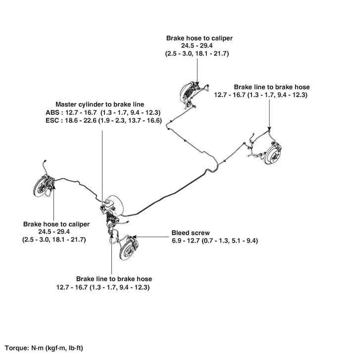
| Components |
Repair procedures
| Removal |
| 1. | Remove the brake fluid level sensor connector.
|

| 2. | Remove the brake fluid from the master cylinder reservoir with a syringe.
|

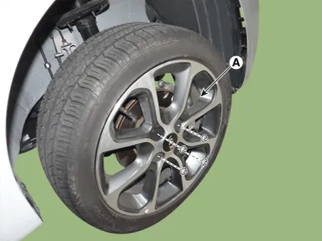
| 3. | Remove the front/rear wheel tire (A).
[Front]
[Rear]
|

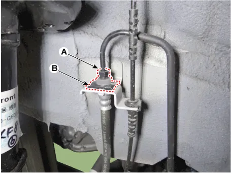
| 4. | Disconnect the brake tube by loosening the tube flare nut (A). |
| 5. | Remove the brake hose clip (B).
|
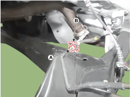
| 6. | Disconnect the brake tube by loosening the tube flare nut (A). |
| 7. | Remove the brake hose clip (B).
|
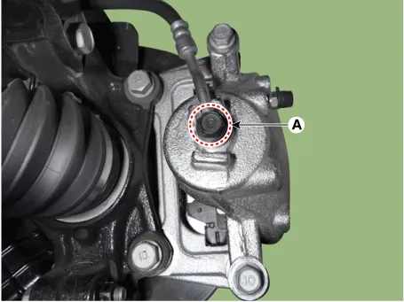
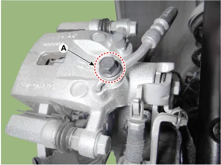
| 8. | Disconnect the brake hose from the brake caliper by loosening the bolt (A).
[Front]
[Rear]
|
| Inspection |
| 1. | Check the brake tubes for cracks, crimps and corrosion. |
| 2. | Check the brake hoses for cracks, damage and fluid leakage. |
| 3. | Check the brake tube flare nuts for damage and fluid leakage. |
| 4. | Check brake hose mounting bracket for crack or deformation. |
| Installation |
| 1. | Install in the reverse order of removal.
|

| 2. | After installation, bleed the brake system.
(Refer to Brake system - "Brake System")
|
| 3. | Check the spilled brake oil. |
Components and components location Components 1. Brake booster assembly 2. Reservoir 3. Master cylinder Repair procedures Removal 1.
Components and components location Components 1. Brake member assembly 2. Stop lamp switch 3. Brake Pedal Arm Assembly 4. Brake pedal Pad Repair procedures Removal 1.
Other information:
Kia Picanto (JA) 2017-2026 Service & Repair Manual: Power Window Motor
Components and components location Components [Standard Window Motor] [Safety Window Motor] Repair procedures Inspection • When removing with a flat-tip screwdriver or remover, wrap protective tape around the tools to prevent damage to components.
Kia Picanto (JA) 2017-2026 Service & Repair Manual: Rear Glass Defogger Switch
Repair procedures Inspection 1.In the body electrical system, failure can be quickly diagnosed by using the vehicle diagnostic system (KDS/GDS).The diagnostic system (KDS/GDS) provides the following information.(1)Self diagnosis : Checking failure and code number (DTC)(2) Current data : Checking the system input/output data state (3)Actuation
Categories
- Manuals Home
- Kia Picanto Owners Manual
- Kia Picanto Service Manual
- To set cruise control speed
- Charging System
- Normal Condition
- New on site
- Most important about car
