Kia Picanto (JA): Brake System / Brake Pedal
Components and components location
| Components |
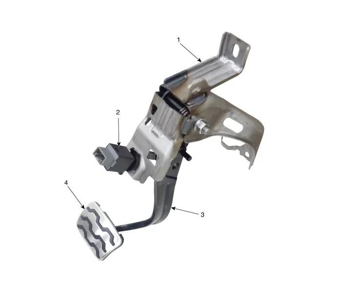
| 1. Brake member assembly 2. Stop lamp switch | 3. Brake Pedal Arm Assembly 4. Brake pedal Pad |
Repair procedures
| Removal |
| 1. | Switch "OFF" ignition and disconnect the negative (-) battery terminal. |
| 2. | Remove the crash pad lower panel.
(Refer to Body - "Crash Pad Lower Panel")
|
| 3. | Remove the steering column.
(Refer to Steering System - "Steering Column and Shaft")
|
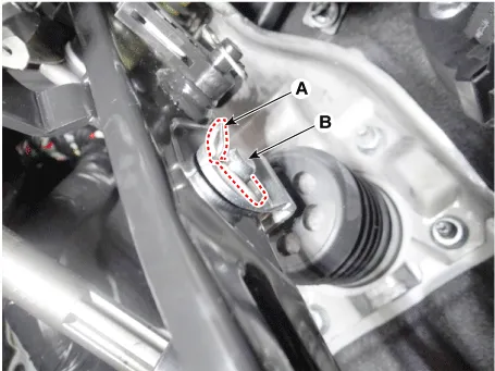
| 4. | Remove the snap pin (A) and clevis pin (B).
|
| 5. | Remove the cable pin from the brake pedal.
|
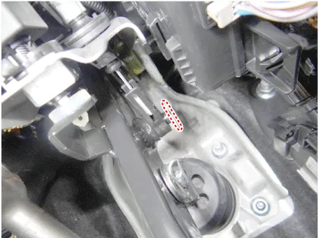
| 6. | Disconnect the clip from the brake pedal .
|
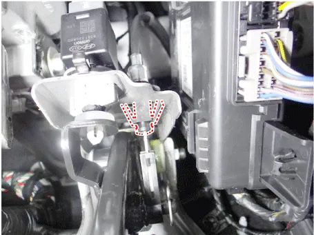
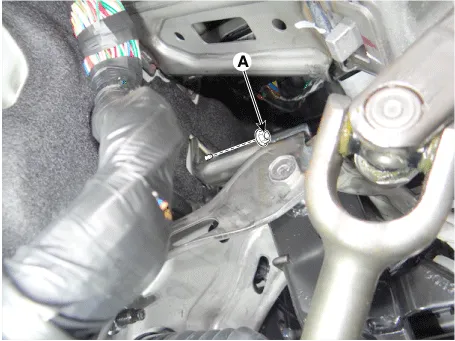
| 7. | Disconnect the stop lamp switch connector (A).
|

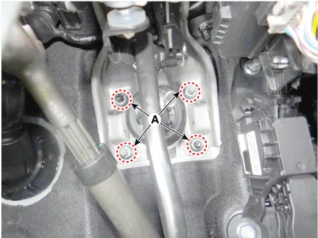
| 8. | Remove the brake pedal mounting nuts (A).
|
| Inspection |
| 1. | Check the bushing for wear. |
| 2. | Check the brake pedal for bending or twisting. |
| 3. | Check the brake pedal return spring for damage. |
| Installation |
| 1. | Install in the reverse order of removal |
Components and components location Components Repair procedures Removal 1.Remove the brake fluid level sensor connector. 2.Remove the brake fluid from the master cylinder reservoir with a syringe.
Components and components location Components 1. Guid bolt 2. Caliper body 3. Caliper member 4. Pad liner 5. Brake pad assembly [OUT] 6. Brake pad assembly [IN] 7.
Other information:
Kia Picanto (JA) 2017-2026 Service & Repair Manual: Power Windows
Components and components location Component Location 1. Driver power window switch 2. Assist power window switch 3. Rear power window switch 4. Front window motor 5. Rear window motor Description and operation Safety Function of Power Window When driver door power window auto-up switch is operated, safety function is acti
Kia Picanto (JA) 2017-2026 Service & Repair Manual: Temperature Control Actuator
Components and components location Component Location 1. Temerature Control Actuator Description and operation Description 1. Heater unit includes mode control actuator and temperature control actuator. 2. Temperature control actuator is located at the heater unit.
Categories
- Manuals Home
- Kia Picanto Owners Manual
- Kia Picanto Service Manual
- To set cruise control speed
- Body Electrical System
- Engine Mechanical System
- New on site
- Most important about car
