Kia Picanto (JA): Front Suspension System / Front Stabilizer Bar
Repair procedures
| Removal |
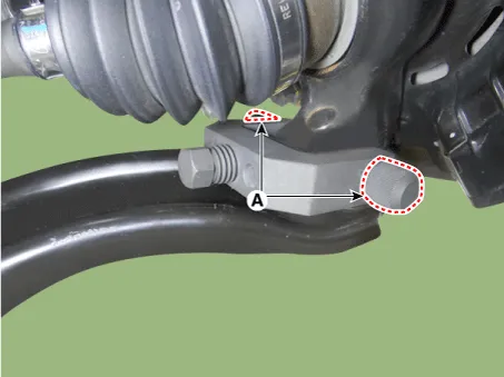
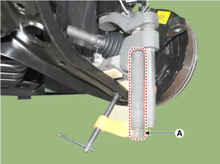
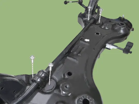
| 1. | Remove the universal joint bolt (A).
|


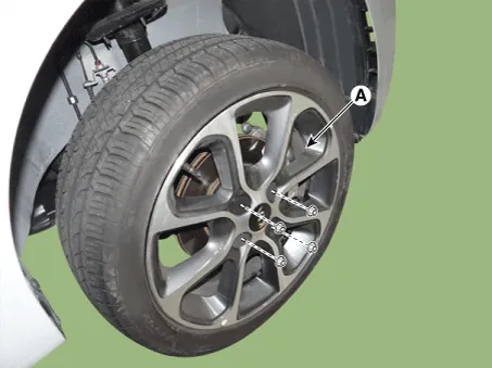
| 2. | Remove the front wheel tire (A).
|
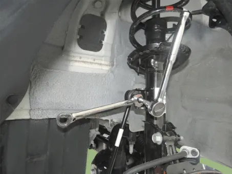
| 3. | Remove the lower arm bolt and nut.
|

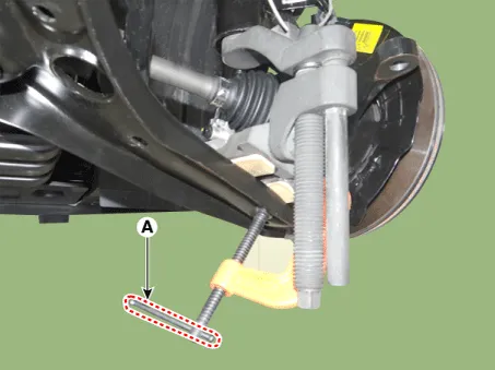
| 4. | Remove the front lower arm from the front knuckle using the SST (0K545-A9100).
|


| 5. | Remove the pin and nut from the tie rod end ball joint.
|
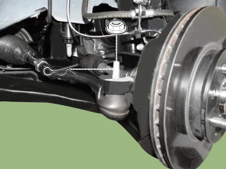
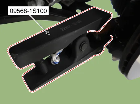
| 6. | Remove the tie rod end ball joint from the knuckle by using the SST (09568-1S100).
|
| 7. | Remove the stabilizer link nut.
|
| 8. | Remove the roll rod bracket.
G 1.0 MPI (Refer to Engine Mechanical System - "Engine Mounting")
G 1.2 MPI (Refer to Engine Mechanical System - "Engine Mounting")
|
| 9. | Remove the muffler hanger.
|

| 10. | Loosen the bolts & nuts and then remove the sub frame (A).
|

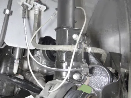
| 11. | Remove the gear box heat protector.
|

| 12. | Loosen the gear box mounting bolts and then remove the gear box.
|

| 13. | Loosen the bolts and then remove the stabilizer bar assembly.
|
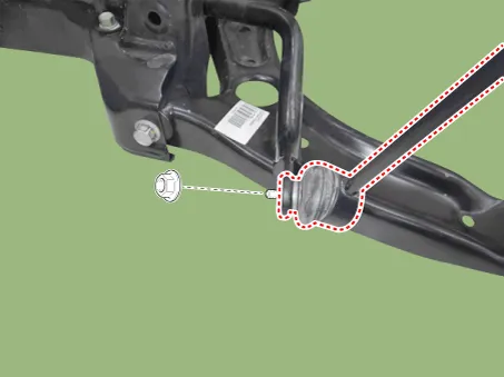
| 14. | Loosen the nut and then remove the stabilizer link.
|
| 15. | Install in the reverse order of removal. |
| 16. | Check the wheel alignment.
(Refer to Tires/Wheels - "Alignment")
|
| Inspection |
| 1. | Check the bushing for wear and deterioration. |
| 2. | Check the front stabilizer bar for deformation. |
| 3. | Check the front stabilizer link ball joint for damage. |
Repair procedures Removal 1.Remove the front/rear wheel tire (A). Tightening torque: 107.9 - 127.5 N·m (11.0 - 13.0 kgf·m, 79.
Repair procedures Removal 1.Remove the universal joint bolt (A). Tightening torque : 32.4 - 37.3 N·m (3.3 - 3.8 kgf·m, 23.9 - 27.
Other information:
Kia Picanto (JA) 2017-2026 Service & Repair Manual: Rear Parking Assist System
Specifications Specification Item Specification Ultrasonic sensor Voltage rating DC 12V Detecting range 11.8 - 39.3 in (30 - 100 cm) Operation voltage DC 9 - 16 V Operation current 60mA Max.
Kia Picanto (JA) 2017-2026 Service & Repair Manual: Power Mosfet
Repair procedures Inspection 1.Ignition "ON" 2.Manually operate the control switch and measure the voltage of blower motor. 3.Select the control switch to raise voltage until high speed. Fan Motor Voltage ManualFirst speed3.
Categories
- Manuals Home
- Kia Picanto Owners Manual
- Kia Picanto Service Manual
- Normal Condition
- To set cruise control speed
- Automatic Transaxle Fluid
- New on site
- Most important about car
