Kia Picanto (JA): Clutch System / Clutch Switch
Specifications
| Specifications |
|
Item
|
Specifications
|
| Working voltage | DC 12.5V |
| Operating force | Initial position : 0.25 ± 0.15 N (0.025 ± 0.015 kg, 0.056 ± 0.034 lb) |
| Full position : 0.8 ± 0.2 N (0.08 ± 0.02 kgf, 0.579 ± 0.014 lb-ft) | |
| Working temperature | -40°C to 80°C (-40°F to 176°F) |
Description and operation
| Description |
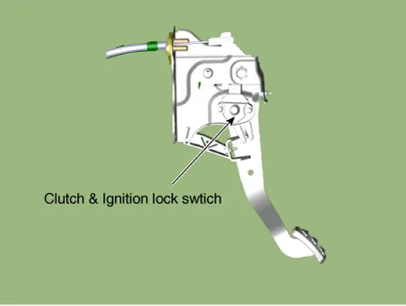
| – | Ignition lock switch is mounted on the clutch pedal. |
| – | Ignition lock switch is operated when you press the clutch pedal. |
| – | If the clutch pedal is not pressed down, the engine is not started. |
Repair procedures
| Inspection |
| 1. | Remove the clutch & ignition lock switch. |
| 2. | Rotate the switch lever to the direction of the arrow to check the operating point (A).
|


| Removal |
| 1. | Turn ignition switch OFF and disconnect the negative (-) battery cable. |
| 2. | Remove the crash pad lower panel.
(Refer to Body - "Crash Pad Lower Panel")
|
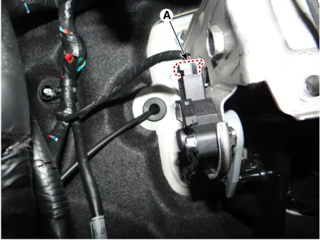
| 3. | Disconnect the cluch switch & ignition lock swtich connector (A).
|
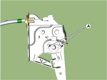
| 4. | Loosen the bolts (A) and then remove the ignition lock switch & clutch switch.
|
| Installation |
| 1. | Install in the reverse order of removal.
|


Specifications Specifications Item Specifications Working voltage DC 12.5V Operating force Initial position : 0.
Components and components location Components [Kappa 1.0 MPI / FFV, Kappa 1.2 MPI] 1. Clutch pedal assembly 2. Clutch cable [Kappa 1.0 T-GDI] 1.
Other information:
Kia Picanto (JA) 2017-2026 Service & Repair Manual: Horn
Components and components location Component Location 1. Horn switch 2. Horn relay 3. Horn 4. Clock spring Repair procedures Removal 1.Disconnect the negative (-) battery terminal. 2.Remove the engine room under cover. G 1.
Kia Picanto (JA) 2017-2026 Service & Repair Manual: Smart Key Diagnostic
Repair procedures Inspection Self Diagnosis With Scan Tool It will be able to diagnose defects of SMART KEY system with KDS/GDS quickly. KDS/GDS can operates actuator forcefully, input/output value monitoring and self diagnosis. The following three features will be major problem in SMART KEY system.
Categories
- Manuals Home
- Kia Picanto Owners Manual
- Kia Picanto Service Manual
- Engine Control / Fuel System
- General Information
- Cooling System
- New on site
- Most important about car
