Kia Picanto (JA): Driveshaft Assembly / TJ Joint
Components and components location
| Components |
| [RH] |

| 1. BJ assembly 2. Clip 3. BJ boot band 4. BJ boot | 5. Dynamic damper band 6. Dynamic damper 7. Shaft 8. TJ boot band | 9. TJ boot 10. Spider assembly 11. Circlip 12. TJ housing | 13. Circlip |
| [LH] |

| 1. BJ assembly 2. BJ circlip 3. BJ boot band 4. BJ boot | 5. Shaft 6. TJ boot band 7. TJ boot 8. Spider assembly | 9. Snap ring 10. TJ case 11. Circlip |
Repair procedures
| Removal |
|

| 1. | Remove the Front Driveshaft.
(Refer to Driveshaft and axle - “Front Driveshaft”)
|
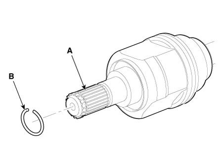
| 2. | Remove the BJ circlip (B) from the TJ housing (A).
|
| 3. | Remove both boot bands from the TJ housing.
|


| 4. | Remove the TJ circlip (A).
|


| 5. | Remove the snap ring (A) and spider assembly (B).
|

| 6. | Clean the spider assembly. |
| 7. | Remove the TJ boot (A).
|
| Inspection |
| 1. | Check the spider assembly for roller rotation, wear or corrosion. |
| 2. | Check the groove inside the joint case for wear or corrosion. |
| 3. | Check the TJ boots for damage and deterioration. |
| Installation |
| 1. | Wrap tape around the driveshaft spline (TJ) to prevent damaging the boot. |
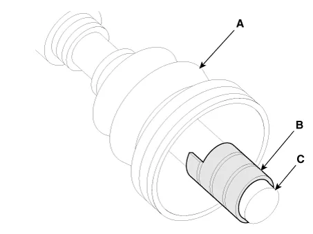
| 2. | Using
the alignment marks (D) made during disassembly as a guide, install the
spider assembly (A) and snap ring (B) on the driveshaft splines (C).
|


| 3. | Add specified grease to the joint boot as much as it was wiped away at inspection. |
| 4. | Install both boot bands. |
| 5. | To control the air in the TJ boot, keep the specified distance between the boot bands when they are tightened.
| |||||||||||||||||||||||

| 6. | Using the SST (09495-3K000), secure the TJ boot bands.
|

| 7. | Install the Front Driveshaft.
(Refer to Driveshaft and axle - “Front Driveshaft”)
|
| 8. | Check the front alignment.
(Refer to Suspension System - "Alignment")
|
Components and components location Components 1. Drive shasft (LH) 2. Drive shaft (RH) [RH] 1. BJ assembly 2. Clip 3. BJ boot band 4.
Components and components location Components [RH] 1. BJ assembly 2. Clip 3. BJ boot band 4. BJ boot 5. Dynamic damper band 6. Dynamic damper 7.
Other information:
Kia Picanto (JA) 2017-2026 Service & Repair Manual: Rear Combination Lamp
Repair procedures Removal 1.Disconnect the negative (-) battery terminal. 2.Remove the rear combination lamp (A) after loosening the screws. 3.Remove the rear combination lamp packing (A). 4.Disconnect the rear combination lamp connector (A).
Kia Picanto (JA) 2017-2026 Service & Repair Manual: Windshield Wiper-Washer Switch
Repair procedures Removal 1.Disconnect the negative (-) battery terminal. 2.Remove the steering column upper and lower shrouds after loosening the screws. (Refer to Body - "Steering Column Shroud Panal") 3.Disconnect the wiper switch / washer switch connector (A).
Categories
- Manuals Home
- Kia Picanto Owners Manual
- Kia Picanto Service Manual
- Charging System
- Engine Oil and Filter
- Clutch Cable
- New on site
- Most important about car
