Kia Picanto (JA): Manual Transaxle Control System / Shift Lever
Components and components location
| Components |
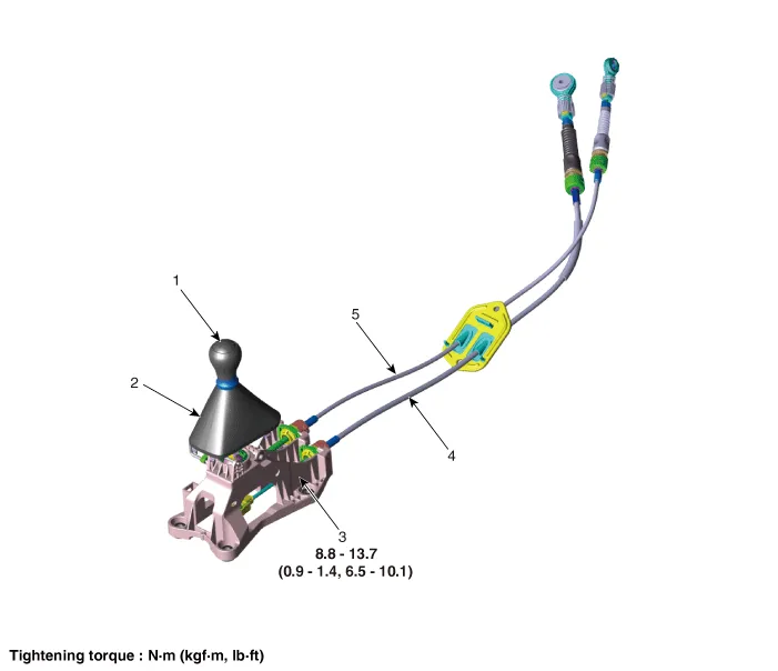
| 1. Knob 2. Boots 3. Shift lever assembly | 4. Shift cable 5. Select cable |
Repair procedures
| Inspection |
| 1. | Check for proper operation of control shaft lever when operated (1st, 2nd, 3rd, 4th, 5th, R). |
| 2. | When the shift lever is engaged to "R", check that the skirt is in proper position. |
| 3. | If the gear feels stiff, adjust the control cable length again.
(Refer to Manual Control System - "Control Cable")
|
| Removal |
| 1. | Remove the knob (A) by pulling it in the direction of arrow.
|
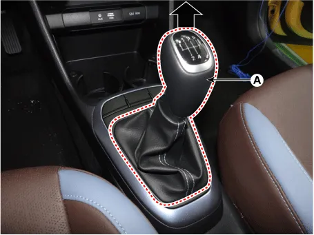
| 2. | Remove the floor console assembly.
(Refer to Body “Floor Console Assembly”)
|
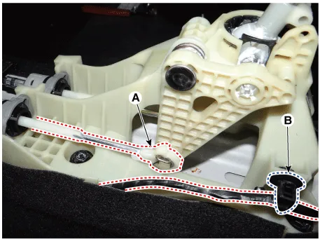
| 3. | Remove the snap pin (A) and then remove the select cable from the shift lever pin. |
| 4. | Remove the wiring fixing clip (B) from the shift lever.
|
| 5. | Remove the cable sockets (A) from the shift lever.
|
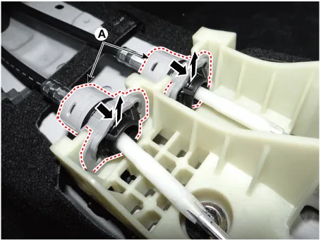
| 6. | Remove the shift cable (A) from the shift lever.
|

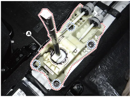
| 7. | Remove the shift lever assembly (A) after loosening the bolts.
|
| Installation |
| 1. | Install in the reverse order of removal. |
Components and components location Components Location 1. Control shaft complete Repair procedures Removal 1.Shift the gear to "neutral".
Components and components location Components 1. Knob 2. Boots 3. Shift lever assembly 4. Shift cable 5. Select cable 6. Retainer Repair procedures Inspection 1.
Other information:
Kia Picanto (JA) 2017-2025 Service & Repair Manual: License Lamps
Repair procedures Removal 1. Disconnect the negative (-) battery terminal. 2. Remove the license lamp assembly (A) after pressing the locking pin. 3. Disconnect the license lamp connector (A). 4. Remove the license lamp bulb (B) after removing the license lamp socket (A).
Kia Picanto (JA) 2017-2025 Service & Repair Manual: Heater & A/C Control Unit(Manual)
Components and components location Components [NON ISG] Connector pin function No. Connector A Connector B 1 Low Battery 2 Common Illumination (+) 3 Ground HTD 4 Middle (Low) ISG Battery 5 Middle (High) - 6 High Detent out (-) 7 - 8 Sen
Categories
- Manuals Home
- Kia Picanto Owners Manual
- Kia Picanto Service Manual
- Indicators And Gauges
- Suspension System
- Fuel Delivery System
- New on site
- Most important about car
