Kia Picanto (JA): Manual Transaxle Control System / Control Cable
Components and components location
| Components |
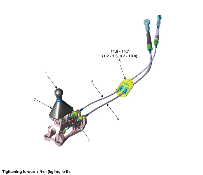
| 1. Knob 2. Boots 3. Shift lever assembly | 4. Shift cable 5. Select cable 6. Retainer |
Repair procedures
| Inspection |
| 1. | Check for proper operation of control shaft lever when operated (1st, 2nd, 3rd, 4th, 5th, R). |
| 2. | If the gear feels stiff, adjust the control cable length again.
(Refer to Manual Control System - "Control Cable")
|
| Adjustment |
| 1. | Move the shift lever to 4th gear. |
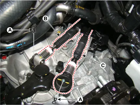
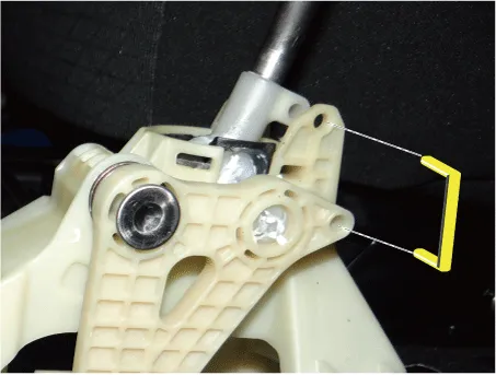
| 2. | Remove the control cable (B) from the control shaft after removing the snap pins (A).
|

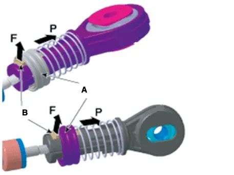
| 3. | After pulling the holder (A) in the direction of the "P", pull the lock (B) in the direction of the "F".
|
| 4. | Insert the snap pins (A).
|

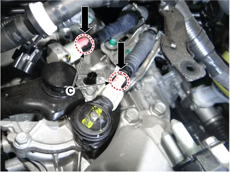
| 5. | Push the lock (C) after installing the control cable to the control shaft.
|
| Removal |
| 1. | Move the shift lever to 4th gear.ove the battery and battery tray. |
| 2. | Remove the battery and battery tray.
G 1.0 T-GDI KAPPA (Refer to Engine Electrical System - "Battery")
|
| 3. | Remove the control cable.
|
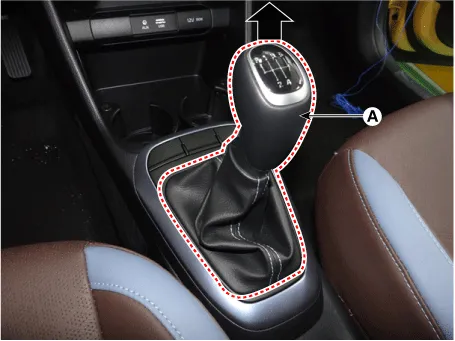
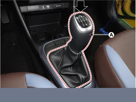
| 4. | Remove the knob (A) by pulling it in the direction of arrow.
|
| 5. | Remove the floor console assembly.
(Refer to Body “Floor Console Assembly”)
|
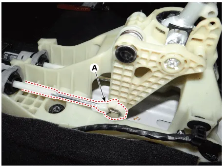
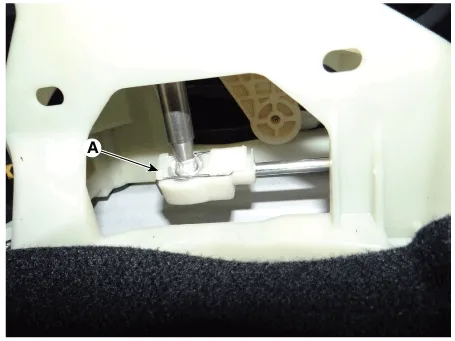
| 6. | Remove the snap pin (A) and then remove the select cable from the shift lever pin.
|
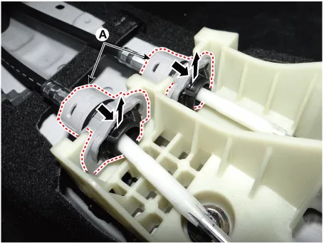
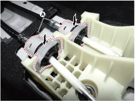
| 7. | Remove the cable sockets (A) from the shift lever.
|
| 8. | Remove the shift lever (A).
|

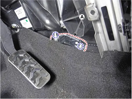
| 9. | Remove
the shift cable retainer (A) after loosening the nuts. Then, remove the
shift cable by pulling it toward the vehicle interior.
|
| Installation |
| 1. | Install the shift cable retainer by tightening nuts (A).
|
| 2. | Install the shift cable (A).
|
| 3. | Install the cable sockets (A).
|
| 4. | Install the select cable to the lever pin and then insert the snap pin (A).
|
| 5. | Check that the shift lever and control shaft are placed in the "4th" position and then install the 4th fixing pin.
|
| 6. | Install the control cable.
|
| 7. | Remove the 4th fixing pin (A).
|
| 8. | Install the floor console assembly.
(Refer to Body - "Floor Console Assembly")
|
| 9. | Install the knob (A) by pressing it in the direction of arrow.
|
| 10. | Install the battery and battery tray.
G 1.0 T-GDI KAPPA (Refer to Engine Electrical System - "Battery")
|
Components and components location Components 1. Knob 2. Boots 3. Shift lever assembly 4. Shift cable 5. Select cable Repair procedures Inspection 1.
Other information:
Kia Picanto (JA) 2017-2026 Service & Repair Manual: Blower Resistor (Manual)
Repair procedures Inspection 1.Measure terminal - to - terminal resistance of blower resistor. 2.measured resistance is not within specification, the blower resistor must be replaced. (After removing the resistor) Replacement 1.Disconnect the negative (-) battery terminal.
Kia Picanto (JA) 2017-2026 Service & Repair Manual: Heater & A/C Control Unit(Full Automatic)
Components and components location Components Control Panel Connector pin function No. Connector A Connector B 1 Battery PAB IGN1 2 ISG Battery (+) PAB On signal 3 Illumination (+) PAB Off signal 4 Sensor REF (+5V) - 5 Mode control actua
Categories
- Manuals Home
- Kia Picanto Owners Manual
- Kia Picanto Service Manual
- Timing Chain
- Coolant
- Cylinder Head
- New on site
- Most important about car
