Kia Picanto (JA): Cylinder Block Assembly / Water Jacket Insert
Repair procedures
| Removal and Installation |
| 1. | Remove the cylinder head assembly.
(Refer to Cylinder Head Assembly - "Cylinder Head")
|
| 2. | Remove the water jacket insert inlet (A) and water jacket insert (B).
|
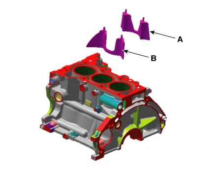

| 3. | Install in the reverse order of removal. |
Repair procedures Removal and Installation 1.Remove the manual transaxle assembly. (Refer to Manual Transaxle System - "Manual Transaxle") 2.
Repair procedures Replacement 1.Remove the transaxle assembly. (Refer to Manual Transaxle System - "Manual Transaxle") 2.Remove the flywheel.
Other information:
Kia Picanto (JA) 2017-2026 Service & Repair Manual: Emergency Call (eCall) Unit
Components and components location Component The eCall unit for AVN is equipped in AVN head unit. Repair procedures Removal Carry out the Test Mode in the following cases.– Replacing the eCall unit– Replacing the Bac
Kia Picanto (JA) 2017-2026 Service & Repair Manual: Intake Actuator
Components and components location Component Location 1. Intake Actuator Description and operation Description 1. The intake actuator is located at the blower unit. 2. It regulates the intake door by signal from control unit.
Categories
- Manuals Home
- Kia Picanto Owners Manual
- Kia Picanto Service Manual
- Normal Condition
- Suspension System
- Cylinder Head
- New on site
- Most important about car
