Kia Picanto (JA): Cylinder Block Assembly / Flywheel
Repair procedures
| Removal and Installation |
| 1. | Remove the manual transaxle assembly.
(Refer to Manual Transaxle System - "Manual Transaxle")
|
| 2. | Remove the clutch cover.
(Refer to Clutch System - "Clutch Cover and Disc")
|
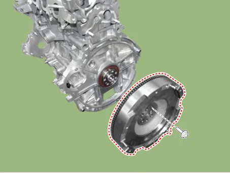
| 3. | Remove the flywheel (A).
|

| 4. | Install in the reverse order of removal. |
Components and components location Components 1. Water jacket insert 2. Water jacket insert inlet 3. Cylinder block 4. O-ring 5. Oil jet 6. Thrust bearing 7.
Repair procedures Removal and Installation 1.Remove the cylinder head assembly. (Refer to Cylinder Head Assembly - "Cylinder Head") 2.
Other information:
Kia Picanto (JA) 2017-2026 Service & Repair Manual: Emergency Call (eCall) Unit
Components and components location Component The eCall unit for AVN is equipped in AVN head unit. Repair procedures Removal Carry out the Test Mode in the following cases.– Replacing the eCall unit– Replacing the Bac
Kia Picanto (JA) 2017-2026 Service & Repair Manual: Seat Heater Switch
Components and components location Components 1. Driver side seat heater switch 2. Passenger side seat heater switch Schematic diagrams Circuit Diagram Repair procedures Removal 1. Disconnect the negative (-) battery terminal.
Categories
- Manuals Home
- Kia Picanto Owners Manual
- Kia Picanto Service Manual
- Suspension System
- To set cruise control speed
- Thermostat
- New on site
- Most important about car
