Kia Picanto (JA): Motor Driven Power Steering / Steering Column and Shaft
Repair procedures
| Removal |
| 1. | Disconnect the battery negative cable. |
| 2. | Turn the steering wheel so that the front wheels are facing straight ahead. |
| 3. | Remove the driver airbag module.
(Refer to Restraint - "Driver Airbag (DAB) Module and Clock Spring")
|
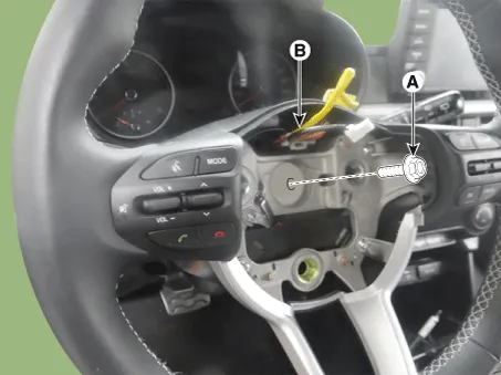
| 4. | Remove the steering wheel lock bolt (A) and clock spring connector (B) from the steering wheel.
|

| 5. | Remove the crash pad lower panel.
(Refer to Body - "Crash pad lower panel")
|
| 6. | Loosen the screw (A) and then remove the shroud cover.
|

| 7. | Remove the clock spring.
(Refer to Restraint - "Driver Airbag (DAB) Module and Clock Spring")
|
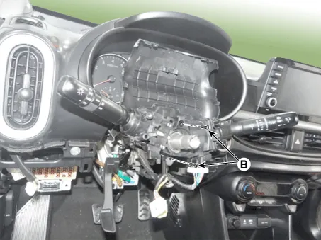
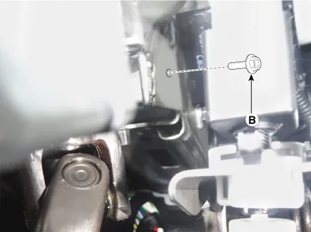
| 8. | Disconnect the multi funtion switch connector (A) and then loosen the screws (B).
|
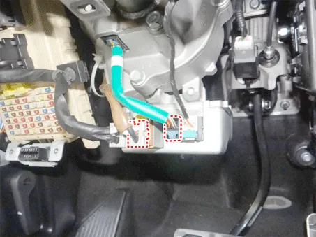
| 9. | Disconnect the MDPS ECU connector.
|
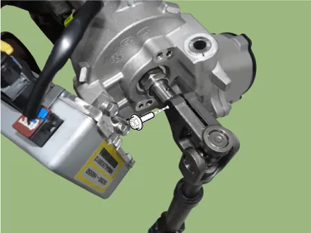
| 10. | Loosen the universal joint bolt (A).
|


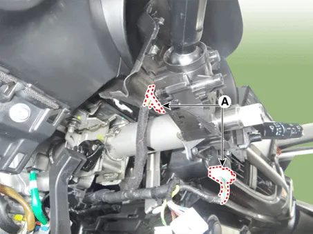
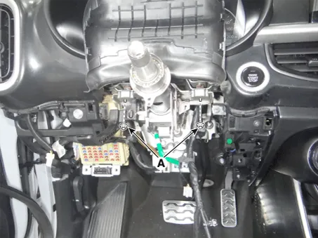
| 11. | Loosen the nuts (A) and bolt (B) and then remove the steering column assembly.
|
| 12. | Install in the reverse order of removal. |
| 13. | Register "ASP calibration EPS type recognition" by GDS after replacing steering column assembly. (Refer to Electric Power Steering - "Repair procedures") |
| Disassembly |
| 1. | Loosen the bolt and then disconnect the universal joint assembly from the steering column assembly.
|
| 2. | Install in the reverse order of removal. |
| Inspection |
| 1. | Check the steering column for damage and deformation. |
| 2. | Check the joint bearing for damage and wear. |
| 3. | Check the tilt bracket for damage and cracks. |
| Diagnosis with KDS |
|
| 1. | Connect
self-diagnosis connector (16pins) located under the driver side crash
pad to self-diagnosis device, and then turn the self-diagnosis device
after key is ON. |
| 2. | Select the "vehicle model" and "Motor Driven Power Steering" on KDS vehicle selection screen. |
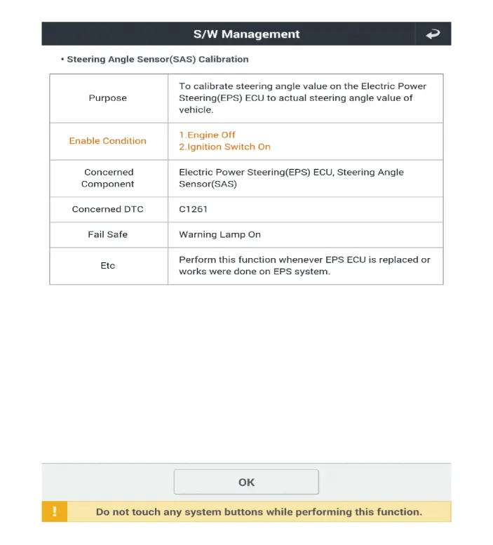
| 3. | Select the "Steering Angle Sensor (SAS) Calibration" on KDS screen, then select OK. |
| 4. | Proceed with the test according to the screen instructions.
|


|
| 1. | Connect
self-diagnosis connector (16pins) located under the driver side crash
pad to self-diagnosis device, and then turn the self-diagnosis device
after key is ON. |
| 2. | Select the "vehicle model" and "Motor Driven Power Steering" on KDS vehicle selection screen. |
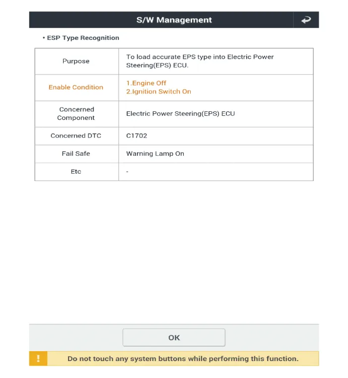
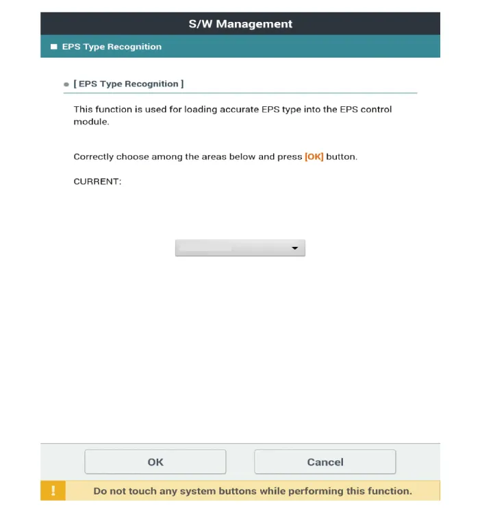
| 3. | Select the "EPS Type Recognition" on KDS screen, then select OK. |
| 4. | Proceed with the test according to the screen instructions.
|


| 5. | Remove the DTC. |
| 6. | Turn off the IG switch and wait for 10 seconds or more before starting the engine. And then make sure that MDPS works properly. |
Repair procedures Removal 1. Remove the steering column and shaft assembly. (Refer to Motor Driven Power Steering - "Steering Column and Shaft") 2.
Repair procedures Removal 1.Remove the universal joint bolt (A). Tightening torque : 32.4 - 37.3 N·m (3.3 - 3.8 kgf·m, 23.9 - 27.
Other information:
Kia Picanto (JA) 2017-2026 Service & Repair Manual: Rear Wiper Motor
Repair procedures Inspection Rear Wiper Motor 1.Remove the connector from the rear wiper motor. 2.Connect positive (+) battery cables to terminal 1 and negative (-) battery cables to terminal 2 respectively. 3.Check that the motor operates normally.
Kia Picanto (JA) 2017-2026 Service & Repair Manual: Smart Key
Repair procedures Smart Key Smart Key Code Saving 1. Connect the DLC cable of KDS/GDS to the data link connector (16 pins) in driver side crash pad lower panel, turn the power on KDS/GDS. 2. Select the vehicle model and then do "Smart key code saving".
Categories
- Manuals Home
- Kia Picanto Owners Manual
- Kia Picanto Service Manual
- Cylinder Head
- Thermostat
- Timing Chain
- New on site
- Most important about car
