Kia Picanto (JA): Smart Key System / Smart Key
Repair procedures
| Smart Key |
| 1. | Connect
the DLC cable of KDS/GDS to the data link connector (16 pins) in driver
side crash pad lower panel, turn the power on KDS/GDS.
|

| 2. | Select the vehicle model and then do "Smart key code saving".
|

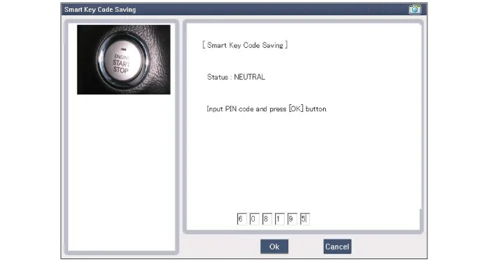
| 3. | After selecting "Smart key teaching" menu, push "Enter" key, then the screen will be shown as below.
|

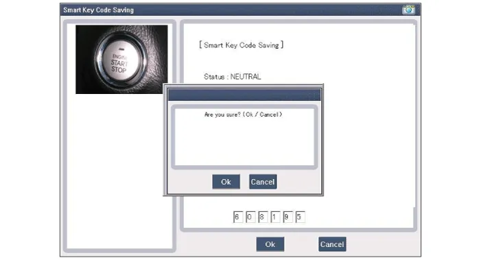
| 4. | After having the teaching smart key, push "ENTER" key. |
| 5. | Input the "Pin code" for first key teaching.
|
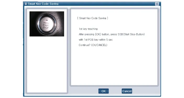
| 6. | Press the SSB with smart key within 5 sec after pressing "OK".
|
| 7. | Confirm the message "First key teaching completed".
|
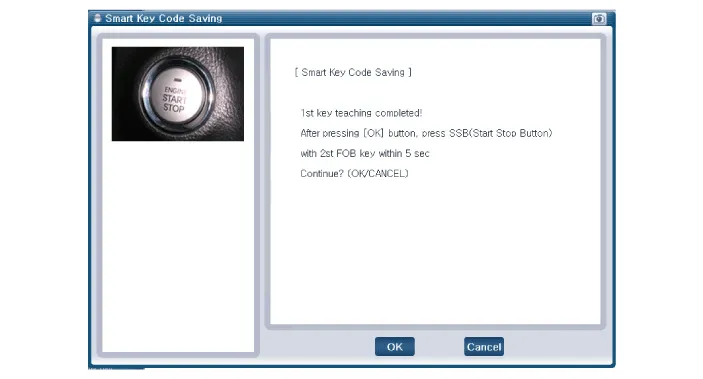
| 8. | Press the SSB with smart key within 5 sec after pressing "OK".
|
| 9. | Confirm the message "Second key teaching completed".
|

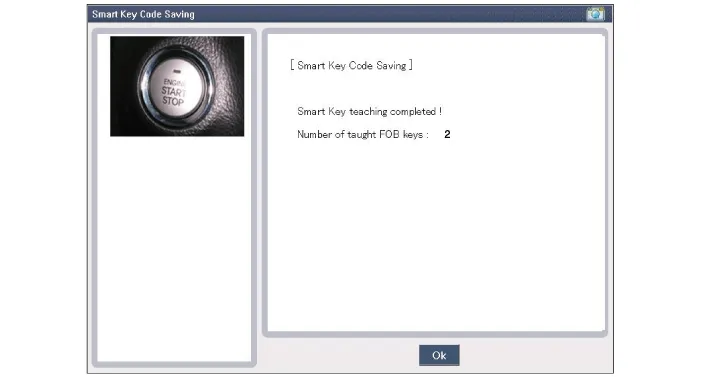
| 10. | Then the screen will be shown as below when key teaching process is completed.
|
Specifications Specifications Smart Key Unit Items Specification Rated voltage DC 12 V Operating voltage DC 9 - 16 V Operating temperature -31 - 167°F (-35 - 75°C) Load Max.
Components and components location Components Connector Pin Information No. Connector A Connector B Connector C 1 - IGN2 Relay_output Battery (+)_Signal 2 SSB Switch1 signal_input P-CAN (Low) - 3 Driver door outside handle switch_input P-CAN (High) Immobilizer antenna (Power)_output 4 - C-CAN (High) Driver outside handle antenna (Power)_output 5 - C-CAN (Low) Passenger outside handle antenna (Power)_output 6 - SSB Amber illumination_output Bumper antenna (Power)_output 7 RPM Signal_input - Interior antenna 1 (Power)_output 8 Start signal feedback_input SSB Illumination (+)_output Interior antenna 2 (Power)_output 9 IGN2 ESCL Enable_output - 10 - Battery (+)_Power - 11 Starter relay_output IGN1 Relay_output - 12 Ground_Power1 ESCL (COM) - 13 SSB Switch2 signal_input EMS (COM) ESCL_Ground (-)_output 14 Assist door outside handle switch_input - Immobilizer antenna (Ground)_output 15 - SSB Illumination (-)_output Driver outside handle antenna (Ground)_output 16 AT : "P" Positon_input MT : Clutch switch_input SSB Illumination (Blue)_output SSB Illumination (Red)_output Passenger outside handle antenna (Ground)_output 17 ESCL Unlock switch_input - Bumper antenna (Ground)_output 18 Wheel speed sensor_input Exterior buzzer_output Interior antenna 1 (Ground)_output 19 ACC Signal_input - Interior antenna 2 (Ground)_output 20 IGN1 ESCL (+)_output - 21 Brake switch_input - 22 ACC Relay_output Ground_Power2 Schematic diagrams Circuit Diagram Repair procedures Removal Put on gloves to prevent hand injuries.
Other information:
Kia Picanto (JA) 2017-2026 Service & Repair Manual: Multimedia Jack
Schematic diagrams Circuit Diagram Description and operation Description The multimedia jack on the console upper cover is for customers who like to listen to external portable music players like the MP3 etc., through the vehicle's sound system when it is linked to this jack.
Kia Picanto (JA) 2017-2026 Service & Repair Manual: Smart Key System
Specifications Specifications Smart Key Unit Items Specification Rated voltage DC 12 V Operating voltage DC 9 - 16 V Operating temperature -31 - 167°F (-35 - 75°C) Load Max. 4mA (When welcome light function "OFF") RF Receiver Items
Categories
- Manuals Home
- Kia Picanto Owners Manual
- Kia Picanto Service Manual
- Charging System
- Body Electrical System
- Cylinder Head
- New on site
- Most important about car
