Kia Picanto (JA): Motor Driven Power Steering / Steering Gear box
Repair procedures
| Removal |
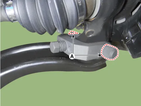
| 1. | Remove the universal joint bolt (A).
|


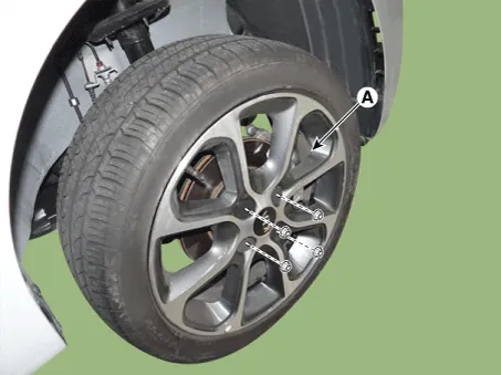
| 2. | Remove the front/rear wheel tire (A).
|

| 3. | Remove the lower arm bolt and nut.
|

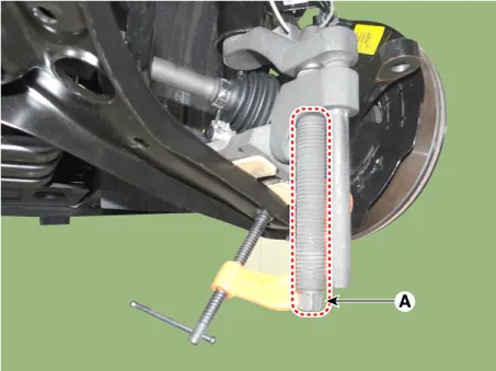
| 4. | Remove the front lower arm from the front knuckle using the SST (0K545-A9100).
|


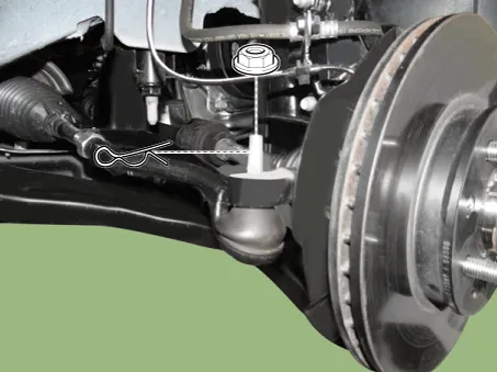
| 5. | Remove the pin and nut from the tie rod end ball joint.
|
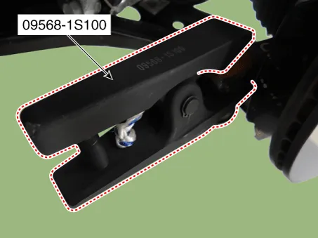
| 6. | Remove the tie rod end ball joint from the knuckle by using the SST (09568-1S100).
|
| 7. | Remove the stabilizer link nut.
|
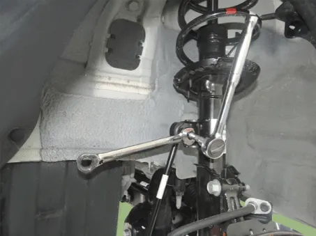
| 8. | Remove the roll rod bracket.
G 1.0 MPI (Refer to Engine Mechanical System - "Engine Mounting")
G 1.2 MPI (Refer to Engine Mechanical System - "Engine Mounting")
|
| 9. | Remove the muffler hanger.
|

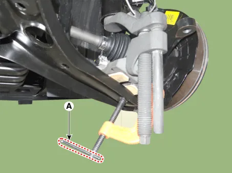
| 10. | Loosen the bolts & nuts and then remove the sub frame (A).
|

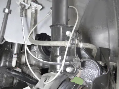
| 11. | Remove the gear box heat protector.
|

| 12. | Loosen the gear box mounting bolts and then remove the gear box.
|

| 13. | Install in the reverse order of removal. |
| 14. | Check the wheel alignment.
(Refer to Tires/Wheels - "Alignment")
|
Repair procedures Removal 1.Disconnect the battery negative cable. 2.Turn the steering wheel so that the front wheels are facing straight ahead.
General information General The supplemental restraint system (SRS) is designed to supplement the seat belt to help reduce the risk or severity of injury to the driver and passenger by activating and deploying the driver, passenger, side airbag and belt pretensioner in certain frontal or side collisions.
Other information:
Kia Picanto (JA) 2017-2026 Service & Repair Manual: Ignition Switch Assembly
Repair procedures Inspection 1.Disconnect the key warning switch connector (A) and ignition switch connector (B) from the steering column. 2.Check for continuity between the terminals. 3.If continuity is not specified, replace the switch.
Kia Picanto (JA) 2017-2026 Service & Repair Manual: Intake Actuator
Components and components location Component Location 1. Intake Actuator Description and operation Description 1. The intake actuator is located at the blower unit. 2. It regulates the intake door by signal from control unit.
Categories
- Manuals Home
- Kia Picanto Owners Manual
- Kia Picanto Service Manual
- To set cruise control speed
- Fuel Delivery System
- Engine Oil and Filter
- New on site
- Most important about car
