Kia Picanto (JA): SRSCM / SRS Control Module (SRSCM)
Description and operation
The
primary purpose of the SRSCM (Supplemental Restraints System Control
Module) is to discriminate between an event that warrants restraint
system deployment and an event that does not. The SRSCM must decide
whether to deploy the restraint system or not. After determining that
pretensioners and/or airbag deployment is required, the SRSCM must
supply sufficient power to the pretensioners and airbag igniters to
initiate deployment.
The
SRSCM determines that an impact may require deployment of the
pretensioners and airbags from data obtained from impact sensors and
other components in conjunction with a safing function.
The
SRSCM will not be ready to detect a crash or to activate the restraint
system devices until the signals in the SRSCM circuitry stabilize.
It
is possible that the SRSCM could activate the safety restraint devices
in approximately 3 seconds but is guaranteed to fully function after
prove-out is completed.
The
SRSCM must perform a diagnostic routine and light a system readiness
indicator at key-on. The system must perform a continuous diagnostic
routine and provide fault annunciation through a warning lamp indicator
in the event of fault detection. A serial diagnostic communication
interface will be used to facilitate servicing of the restraint control
system.
Components and components location

1. Supplemental Restraint System Control Module
|
Repair procedures
| 1. | Remove the ignition key from the vehicle. |
| 2. | Disconnect the battery negative cable and wait for at least three minutes before beginning work. |
| 3. | Remove the floor console assembly.
(Refer to Body - "Floor Console Assembly")
|
| 4. | Disconnect the Supplemental Restraint System Control Module (SRSCM) connector (A).
 |
| 5. | Loosen the bolts and then remove the supplemental restraint system control module (A).
 |
| 6. | Install in the reverse order of removal. |
After replacing the SRSCM with a new one, must be performed the “Variant Coding” procedure.
| 1) | On
SRSCM variant coding mode, the airbag warning lamp is periodically
blinking (ON: 0.5sec., OFF: 0.5sec.) until the coding is normally
completed. |
| 2) | If the variant coding is failed, DTC B1762 (ACU Coding Error) will be displayed and the warning lamp will be turned on. In this case, perform the variant coding procedure again after confirming the cause in “DTC Fault State Information”. Variant
Coding can be performed up to 255 times, but if the number of coding
work exceeds 255 times, DTC B1683 (Exceed Maximum coding Number) will be
displayed and SRSCM must be replaced. |
| 3) |
If the battery voltage is low (less than 9V), DTC B1102 will be
displayed. In this case, charge the battery before anything else, and
then perform the variant coding procedure. DTC B1762 (ACU Coding Error) and B1102 (Battery Voltage Low) may be displayed simultaneously. |
|
Variant coding Procedure
| 1. | Ignition "OFF", connect GDS. |
| 2. | Ignition "ON" & Engine "OFF" select vehicle name and airbag system. |
| 3. | Select Variant coding mode. |
| 4. | Follow steps on the screen as below. |
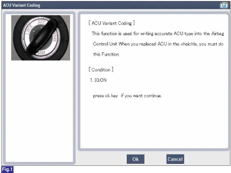
1) Initial ACU Variant Coding screen
2) VIN Code entering screen

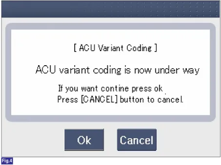
3) Variant coding's proceeding screen-1

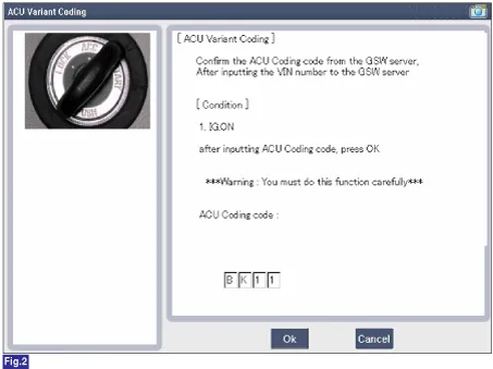
4) Variant coding's proceeding screen-2
5) Variant coding is completed

1) This screen is opened when you try the variant coding again on the SRSCM which has bee performed variant coding.
 2) Screen of communication failure
 |
■ Off-line type on GDS (This can be used when not connecting to internet)
1) Initial ACU Variant Coding screen

2) ACU Coding Code entering screen
3) Screen of rechecking ACU Coding code's entering

4) Variant coding's proceeding screen-1

5) Variant coding's proceeding screen-2

6) Variant coding is completed

1) This screen is opened when you try the variant coding again on the SRSCM which has bee performed variant coding.
 |
Description and operation
Description
•
The front impact sensor (FIS) is installed in the Front End Module (FEM).
Other information:
Troubleshooting
Troubleshooting
Error Item
Failure symptom
Inspection items
Detailed inspections
Relevant Parts/
Components
Screen display LCD scree
Repair procedures
Removal
1.Disconnect the negative (-) battery terminal.
2.Remove the rear combination lamp (A) after loosening the screws.
3.Remove the rear combination lamp packing (A).
4.Disconnect the rear combination lamp connector (A).

