Kia Picanto (JA): SRSCM / Front Impact Sensor (FIS)
Description and operation
| Description |
| • | The front impact sensor (FIS) is installed in the Front End Module (FEM). |
| • | FIS is a remote sensor that detects acceleration due to a collision at its mounting location. |
| • |
The primary purpose of the Front Impact Sensor (FIS) is to provide an
indication of a collision. The Front Impact Sensor (FIS) sends
acceleration data to the SRSCM. |
Components and components location
| Components |

| 1. Front Impact Sensor (FIS) |
Repair procedures
| Replacement |
| 1. | Disconnect the negative battery cable and wait for at least thirty seconds before beginning to work. |
| 2. | Remove the Head lamp.
(Refer to Body Electrical System - "Head Lamp")
|
| 3. | Make a gap by lossening the washer reservoir tank mounting bolt.
(Refer to Body Electrical System - "Front Washer Motor")
|
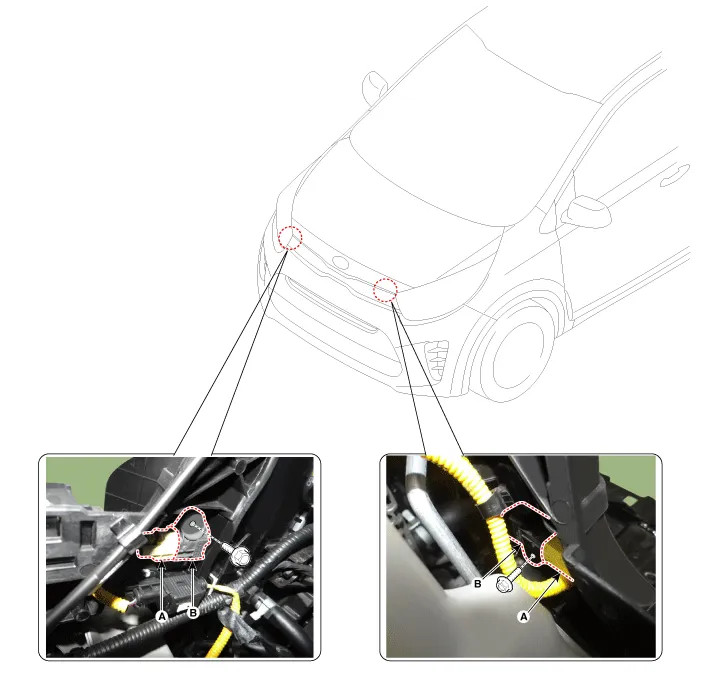
| 4. | Disconnect the front impact sensor connector (A). |
| 5. | Remove the front impact sensor (B) after loosening the mounting bolt.
|
| 6. | Install in the reverse order of removal. |
Description and operation Description The primary purpose of the SRSCM (Supplemental Restraints System Control Module) is to discriminate between an event that warrants restraint system deployment and an event that does not.
Description and operation Description • Side Impact Sensor (SIS) system consists of two Pressure Side Impact Sensor (P-SIS) installed at each center of the front door module (LH and RH), two SIS installed at each center pillar nearby (LH and RH) and two rear SIS installed in the rear pillar (LH and RH).
Other information:
Kia Picanto (JA) 2017-2026 Service & Repair Manual: Rear Glass Defogger Switch
Repair procedures Inspection 1.In the body electrical system, failure can be quickly diagnosed by using the vehicle diagnostic system (KDS/GDS).The diagnostic system (KDS/GDS) provides the following information.(1)Self diagnosis : Checking failure and code number (DTC)(2) Current data : Checking the system input/output data state (3)Actuation
Kia Picanto (JA) 2017-2026 Service & Repair Manual: Blower Unit
Components and components location Component Location 1. Blower Unit Components 1. Intake Actuator 2. Intake Case [Lower] 3. Air Filter 4. FET 5. Resister 6. Intake Seal 7. Intake Case [Upper] 8. Intake Door Assembly 9. Anti Noise Pad 10.
Categories
- Manuals Home
- Kia Picanto Owners Manual
- Kia Picanto Service Manual
- Timing Chain
- Front Disc Brake
- Heating,Ventilation, Air Conditioning
- New on site
- Most important about car
