Kia Picanto (JA): SRSCM / Side Impact Sensor (SIS)
Description and operation
| Description |
| • |
Side Impact Sensor (SIS) system consists of two Pressure Side Impact
Sensor (P-SIS) installed at each center of the front door module (LH and
RH), two SIS installed at each center pillar nearby (LH and RH) and two
rear SIS installed in the rear pillar (LH and RH). |
| • | Pressure Side Impact Sensor is also called P-SIS because it detects pressure from collision at its mounting location. |
| • | Side Impact Sensor is also called A-SIS because it detects acceleration. |
| • |
SRSCM decides deployment of the airbag and the time of deployment
through the collision signal of the SIS when the collision occurred. |
Components and components location
| Components |
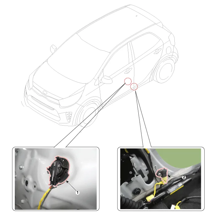
| 1. Front Pressure Side Impact Sensor (P-SIS) | 2. Front Gravity Side Impact Sensor (G-SIS) |
Repair procedures
| Replacement |
| 1. | Disconnect the battery negative cable and wait for at least three minutes before beginning work. |
| 2. | Remove the front door trim.
(Refer to Body - "Front Door Trim")
|
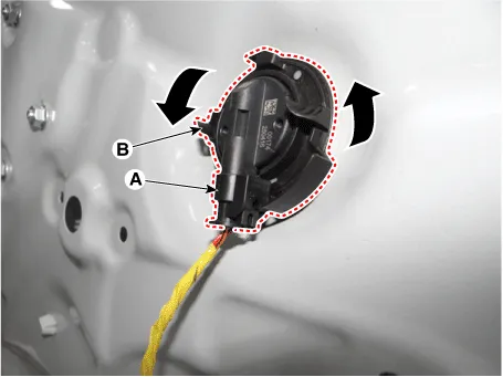
| 3. | Disconnect the pressure side impact sensor connector (A). |
| 4. | Separate the Front pressure side impact sensor (B) after rotating it 90° in a counterclockwise direction.
|
| 5. | Install in the reverse order of removal. |
| 1. | Disconnect the battery negative cable and wait for at least three minutes before beginning work. |
| 2. | Remove the center pillar trim.
(Refer to Body - "Center Pillar Trim")
|
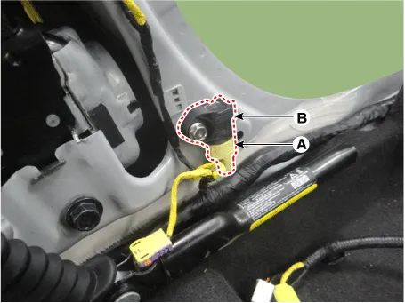
| 3. | Disconnect the side impact sensor connector (A). |
| 4. | Remove the side impact sensor (B) after loosening the mounting bolt.
|
| 5. | Install in the reverse order of removal. |
Description and operation Description • The front impact sensor (FIS) is installed in the Front End Module (FEM).
Description and operation Description The SRSCM shall monitor the status of the driver and front passenger seat belt buckle. The SRSCM provides one pin each for the driver and front passenger seat belt buckle status input.
Other information:
Kia Picanto (JA) 2017-2026 Service & Repair Manual: License Lamps
Repair procedures Removal 1. Disconnect the negative (-) battery terminal. 2. Remove the license lamp assembly (A) after pressing the locking pin. 3. Disconnect the license lamp connector (A). 4. Remove the license lamp bulb (B) after removing the license lamp socket (A).
Kia Picanto (JA) 2017-2026 Service & Repair Manual: Mode Control Actuator
Components and components location Component Location 1. Mode Control Actuator Description and operation Description The mode control actuator is located at the heater unit. It adjusts position of mode door by operating mode control actuator based on signal of A/C control unit.
Categories
- Manuals Home
- Kia Picanto Owners Manual
- Kia Picanto Service Manual
- Engine Mechanical System
- Battery
- Engine Control / Fuel System
- New on site
- Most important about car
