Kia Picanto (JA): SRSCM / Seat Belt Buckle Switch (BS)
Description and operation
| Description |
Components and components location
| Components |
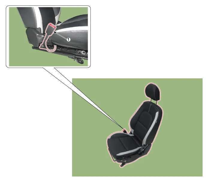
| 1. Seat Belt Buckle Switch (BS) |
Repair procedures
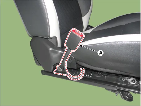
| Removal |
| 1. | Disconnect the battery negative terminal, and wait for at least three minutes before beginning to work. |
| 2. | Remove the front seat assembly.
(Refer to the Body - "Front Seat Assembly")
|
| 3. | Loosen the mouting bolt and then remove the seat belt buckle switch (A).
|
| Installation |
| 1. | Disconnect the battery negative terminal, and wait for at least three minutes before beginning to work. |
| 2. | Install in the reverse order of removal. |
| 3. | Reconnect the battery negative terminal. |
| 4. | After installing the seat belt buckle switch, confirm proper system operation:
|
Description and operation Description • Side Impact Sensor (SIS) system consists of two Pressure Side Impact Sensor (P-SIS) installed at each center of the front door module (LH and RH), two SIS installed at each center pillar nearby (LH and RH) and two rear SIS installed in the rear pillar (LH and RH).
Other information:
Kia Picanto (JA) 2017-2026 Service & Repair Manual: Junction Box (Engine Compartment)
Components and components location Component Location E/R Junction Box Circuit (E/R Junction Block) E/R Junction Box Circuit (E/R Junction Block) Repair procedures Inspection 1. Disconnect the negative (-) battery terminal.
Kia Picanto (JA) 2017-2026 Service & Repair Manual: Power Windows
Components and components location Component Location 1. Driver power window switch 2. Assist power window switch 3. Rear power window switch 4. Front window motor 5. Rear window motor Description and operation Safety Function of Power Window When driver door power window auto-up switch is operated, safety function is acti
Categories
- Manuals Home
- Kia Picanto Owners Manual
- Kia Picanto Service Manual
- Charging System
- Engine Control / Fuel System
- To set cruise control speed
- New on site
- Most important about car
