
Kia Picanto (JA): Manual Transaxle System / Neutral Switch
Specifications
| Specifications |
|
Item
|
Specified
|
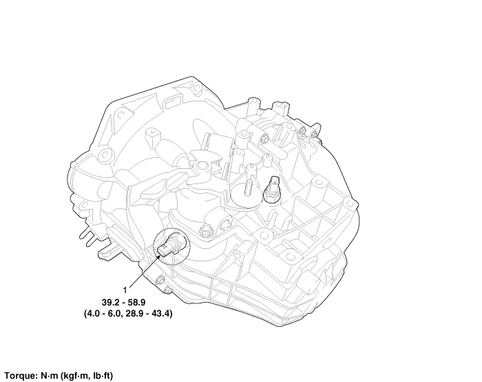
| Type | ON / OFF |
| Operating condition | Neutral gear |
| Operating voltage | 10 V - 15 V |
| Operating temperature | -30°C to 100°C (-30°F to 212°F) |
Components and components location
| Component Location |
Description and operation
| Description |
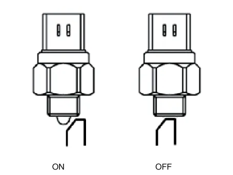
| • | Neutral switch signal is transmitted to ECM in neutral state. |
| • | The signal is blocked when gear is changed. |
| • | When
the signal is blocked, the ECM controls the fuel injection amount
mapping value for 1st gear so that vehicle can start properly.
|
Repair procedures
| Inspection |
| 1. | Remove the battery and battery tray.
G 1.0 T-GDI KAPPA (Refer to Engine Electrical System - "Battery")
|
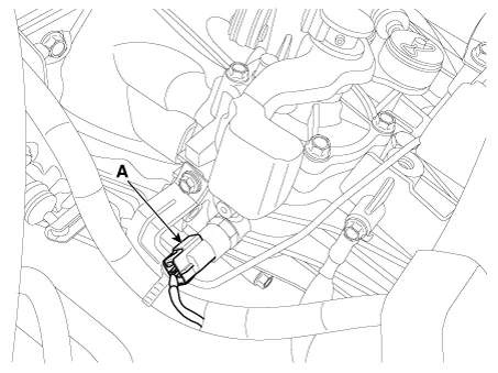
| 2. | Disconnect the neutral switch connector (A).
|
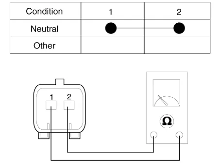
| 3. | Check the continuity between power terminal and signal terminal.
|
| Removal |
| 1. | Remove the battery and battery tray.
G 1.0 T-GDI KAPPA (Refer to Engine Electrical System - "Battery")
|
| 2. | Disconnect the neutral switch connector (A).
|
| 3. | Remove the neutral switch (A).
|

| Installation |
| 1. | Install in the reverse order of removal. |
The neutral switch must be replaced with new one. (Do not reuse it.) |

Specifications Specifications Item Specified Type ON/OFF Operating condition Reverse gear Operating voltage 10V - 15V Operating temperatures -30°C to 100°C [-30°F to 212°F]" Components and components location Component Location 1.
Specifications Specification Engine T/M Joint type Max.
Other information:
Kia Picanto (JA) 2017-2026 Service & Repair Manual: Antenna Coil
Repair procedures Removal 1.Disconnect the negative (-) battery terminal. 2.Remove the crash pad lower panel. (Refer to Body - "Crash Pad Lower Panel") 3.Remove the steering column upper and lower shroud panel. (Refer to Body - "Steering Column Shroud Panel") 4.
Kia Picanto (JA) 2017-2026 Service & Repair Manual: High Mounted Stop Lamp
Repair procedures Removal 1. Disconnect the negative (-) battery terminal. 2. Open the tailgate. 3. Loosen the high mounted stop lamp mounting nuts (A). 4. Disconnect the washer nozzle (A) and high mounted stop lamp connector (B). 5. Remove the high mounted stop lamp (C).
Categories
- Manuals Home
- Kia Picanto Owners Manual
- Kia Picanto Service Manual
- Body Control Module (BCM)
- Suspension System
- Timing Chain
- New on site
- Most important about car
