
Kia Picanto (JA): Manual Transaxle System / Manual Transaxle Oil
Repair procedures
| Inspection |
| 1. | Stop the engine and then raise the vehicle using the lift. |
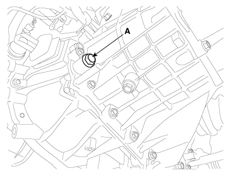
| 2. | Remove the oil filler plug (A).
|
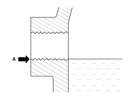
| 3. | Check the condition of the oil and make sure that it is at the proper level (A).
|
| 4. | Install the oil filler plug (A).
|

| Replacement |
| 1. | Stop the engine and then raise the vehicle using the lift. |
| 2. | Remove the drain plug (A), allow the oil to drain out and then reinstall the drain plug.
|
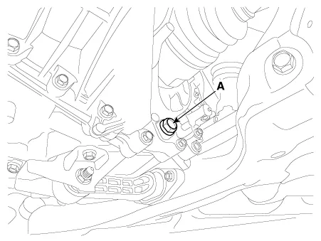
| 3. | Remove the oil filler plug (A).
|
| 4. | Fill the manual transaxle with manual transaxle oil through the filler hole.
|
| 5. | Install the oil filler plug (A).
|
Components and components location Components 1. Control shaft complete 2. Control cable bracket 3. Transaxle support bracket 4. Roll rod bracket 5.
Other information:
Kia Picanto (JA) 2017-2026 Service & Repair Manual: Lighting System
Specifications Specification Item Type Bulb Watt (W) Front Headlamp Halogen (Position lamp) Low/High H4 LL 55/60 Turn signal lamp PY21WLL 21 Position lamp W5WLL 5 Halogen (Position lamp + DRL) Low/High HB3 (9005HL+) 60 Turn signal lamp LED LED Po
Kia Picanto (JA) 2017-2026 Service & Repair Manual: Front Washer Motor
Repair procedures Inspection Front Washer Motor 1.With the washer motor connected to the reservoir tank, fill the reservoir tank with water. • Before filling the reservoir tank with water, check the filter for foreign material or contamination.
Categories
- Manuals Home
- Kia Picanto Owners Manual
- Kia Picanto Service Manual
- Thermostat
- Engine Mechanical System
- Timing Chain
- New on site
- Most important about car
