Kia Picanto (JA): Manual Transaxle System / Manual Transaxle
Components and components location
| Components |
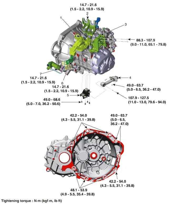
| 1. Control shaft complete 2. Control cable bracket 3. Transaxle support bracket 4. Roll rod bracket | 5. Roll rod support bracket 6. Clutch tube bracket 7. Clutch release cylinder assembly |
Repair procedures
| Removal |
| 1. | Remove the battery and battery tray.
G 1.0 T-GDI KAPPA (Refer to Engine Electrical System - "Battery")
|
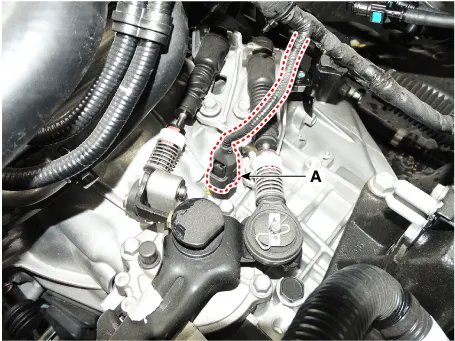
| 2. | Disconnect the back up lamp switch (A).
|
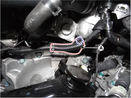
| 3. | Remove the wiring from the bracket (A).
|
| 4. | Remove the control cable.
|
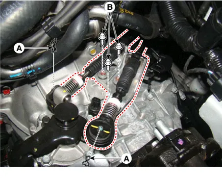
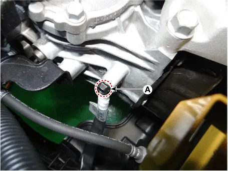
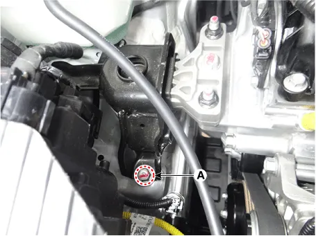
| 5. | Remove the ground bolt (A).
|
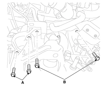
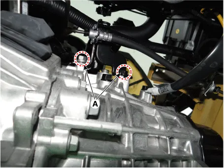
| 6. | Loosen the starter mounting bolts (A) and the transaxle mounting bolts (B).
|
| 7. | Remove the air cleaner assembly.
G 1.0 T-GDI KAPPA (Refer to Engine Mechanical System - "Air Cleaner")
|
| 8. | Remove the cowl top cover.
(Refer to Body - "Cowl Top Cover")
|
| 9. | Remove the wiper motor.
(Refer to Body Electrical System - "Front Wiper Motor")
|
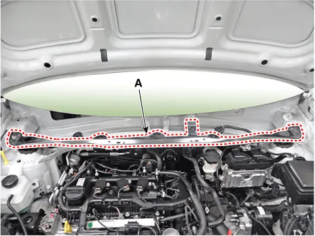
| 10. | Remove the cowl top panel (A).
|
| 11. | Install the engine support fixture on the engine room.
|
| 12. | Support the transaxle safely on a jack.
|
| 13. | Remove the cover (A).
|

| 14. | Loosen the transaxle mounting bracket bolts (A).
|
| 15. | Remove the transaxle support bracket (A).
|

| 16. | Remove the under cover.
G 1.0 T-GDI KAPPA (Refer to Engine Mechanical System - "Engine Room Under Cover")
|
| 17. | Remove the drive shaft assembly.
(Refer to Driveshaft and Axle - "Front Driveshaft")
|
| 18. | Remove the clutch tube bracket bolt (A).
|
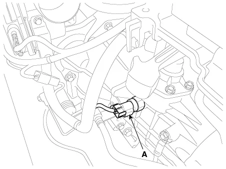
| 19. | Disconnect the neutral switch connector (A).
|
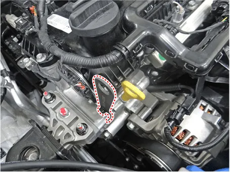
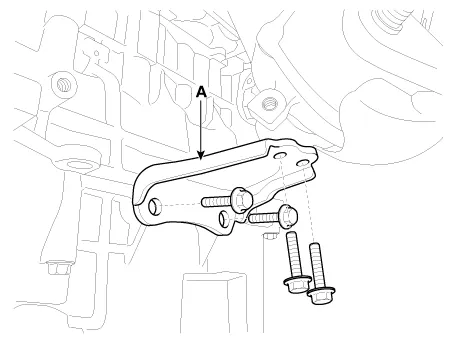
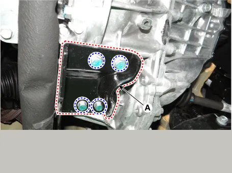
| 20. | Remove the exhaust manifold stay (A).
|
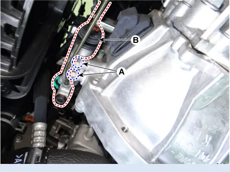
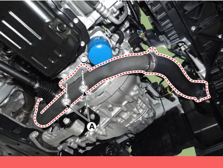
| 21. | Remove the clutch release cylinder assembly (B) after removing the bolts (A).
|
| 22. | Loosen the intercooler pipe mounting bolts (A).
|
| 23. | Remove the roll rod bracket (A) after removing bolt (B, C).
|
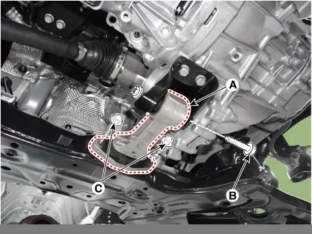
| 24. | Remove the roll rod support bracket (A).
|
| 25. | Support the transaxle safely on a jack. |
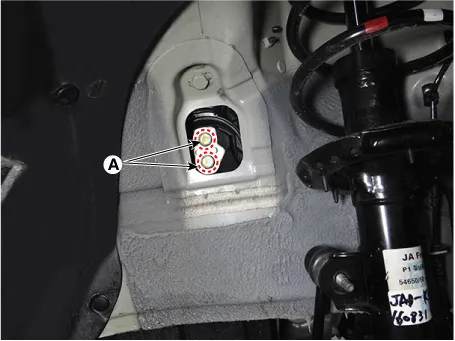
| 26. | Loosen the transaxle lower mounting bolts (A, B).
|
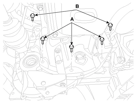
| 27. | After separating the transaxle from the engine, remove the transaxle by lowering the jack slowly.
|

| Installation |
In case of oil leakage due to damaged differential oil seal, replace the oil seal with a new one by using special tools |
| 1. | Install in the reverse order of removal. |
Repair procedures Inspection Manual Transaxle Oil Level Check 1. Stop the engine and then raise the vehicle using the lift. 2. Remove the oil filler plug (A).
Specifications Specifications Item Specified Type ON/OFF Operating condition Reverse gear Operating voltage 10V - 15V Operating temperatures -30°C to 100°C [-30°F to 212°F]" Components and components location Component Location 1.
Other information:
Kia Picanto (JA) 2017-2026 Service & Repair Manual: High Mounted Stop Lamp
Repair procedures Removal 1. Disconnect the negative (-) battery terminal. 2. Open the tailgate. 3. Loosen the high mounted stop lamp mounting nuts (A). 4. Disconnect the washer nozzle (A) and high mounted stop lamp connector (B). 5. Remove the high mounted stop lamp (C).
Kia Picanto (JA) 2017-2026 Service & Repair Manual: Power Window Switch
Components and components location Components Driver Power Window Switch Connector Pin Information [All Manual / Auto Down Type] (LHD) No. Description No.
Categories
- Manuals Home
- Kia Picanto Owners Manual
- Kia Picanto Service Manual
- Suspension System
- Cooling System
- Automatic Transaxle Fluid
- New on site
- Most important about car
