Kia Picanto (JA): Fuel Delivery System / Fuel Tank
Specifications
| Specification |
|
Items
|
Specification
|
| Fuel Tank Capacity (L) | 35 L (9.24 U.S. gal, 37.0 U.S. qt, 30.8 lmp. qt.) |
Repair procedures
| Removal |
| 1. | Release the residual pressure in fuel line.
(Refer to Delivery System - "Release Residual Pressure in Fuel Line”)
|
| 2. | Turn the ignition switch OFF and disconnect the battery negative (-) terminal. |
| 3. | Remove the rear seat cushion.
(Refer to Body - "Rear Seat Assembly")
|
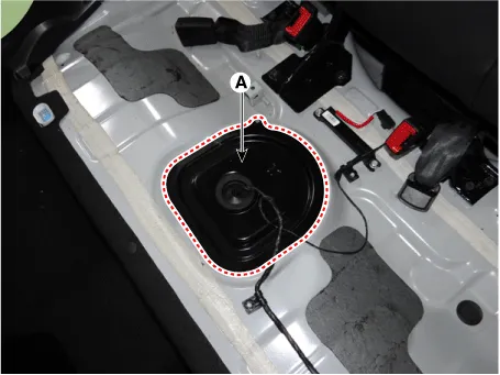
| 4. | Remove the service cover (A).
|
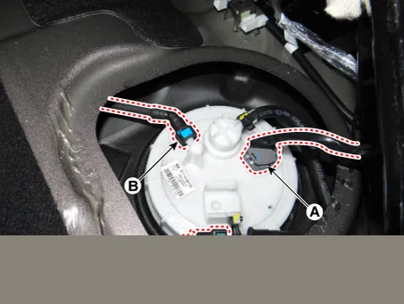
| 5. | Disconnect the fuel pump connector (A). |
| 6. | Disconnect the fuel feed quick-connector (B) and the vapor tube quick-connector (C).
|
| 7. | Remove the center muffler assembly.
(Refer to Engine Mechanical System - "Muffler")
|
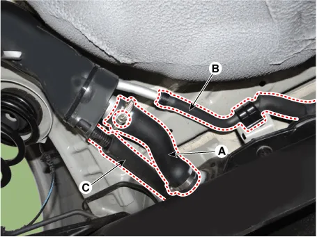
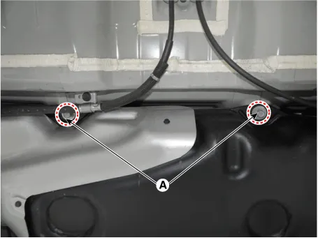
| 8. | Disconnect the fuel filler hose (A), the leveling hose (B) and the vapor hose (C).
|
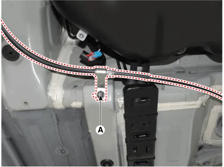
| 9. | Remove the parking brake cable mounting bolt (A).
|
| 10. | Lift the vehicle and support the fuel tank with a jack (A).
|
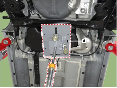
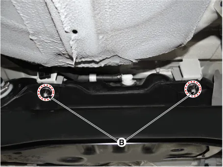
| 11. | Remove the fuel tank mounting bolt (A) and nut (B).
|
| 12. | Remove the fuel tank. |
| Installation |
| 1. | Install in the reverse order of removal. |
Components and components location Components Location Fuel Tank & Filler-Neck Assembly 1. Fuel Tank 2. Fuel Pump 3 Fuel Filter 4.
Repair procedures Inspection [Fuel pump] 1.Turn ignition switch OFF and disconnect the negative (-)battery cable. 2.Remove the fuel pump assembly.
Other information:
Kia Picanto (JA) 2017-2026 Service & Repair Manual: Headlamps
Description and operation Description BI-FUNCTION 1. Definition – A headlamp with integrated functions of high and low beam – The light is controlled by rotating the shield inserted to the lens.
Kia Picanto (JA) 2017-2026 Service & Repair Manual: Front Washer Motor
Repair procedures Inspection Front Washer Motor 1.With the washer motor connected to the reservoir tank, fill the reservoir tank with water. • Before filling the reservoir tank with water, check the filter for foreign material or contamination.
Categories
- Manuals Home
- Kia Picanto Owners Manual
- Kia Picanto Service Manual
- Brake System
- Engine Oil and Filter
- Timing Chain
- New on site
- Most important about car
