Kia Picanto (JA): ABS(Anti-Lock Brake System) / Front Wheel Speed Sensor
Repair procedures
| Removal |
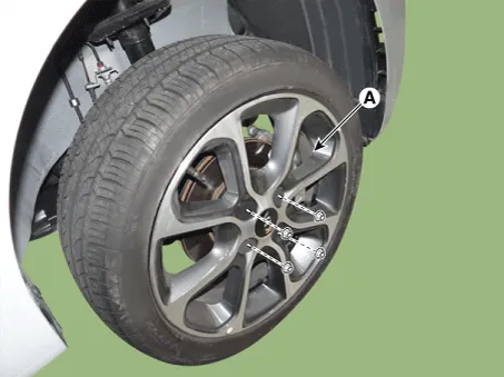
| 1. | Remove the wheel tire (A).
|
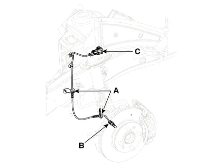
| 2. | Loosen the wheel speed sensor bracket bolts (A),(B) and then disconnect the wheel speed sensor connector (C).
|
| 3. | Install in the reverse order of removal. |
| Inspection |
| 1. | Measure the output voltage between the terminal of the wheel speed sensor and the body ground.
|


| 2. | Compare the change of the output voltage of the wheel speed sensor to the normal change of the output voltage as shown below.
|

Components and components location Components 1. ABS control module connector 2. ABS control module 3. ABS bracket Repair procedures Removal 1.
Repair procedures Removal 1. Remove the wheel tire (A). Tightening torque: 107.9 - 127.5 N·m (11.0 - 13.0 kgf·m, 79.6 - 94.
Other information:
Kia Picanto (JA) 2017-2026 Service & Repair Manual: Ignition Switch Assembly
Repair procedures Inspection 1.Disconnect the key warning switch connector (A) and ignition switch connector (B) from the steering column. 2.Check for continuity between the terminals. 3.If continuity is not specified, replace the switch.
Kia Picanto (JA) 2017-2026 Service & Repair Manual: Mode Control Actuator
Components and components location Component Location 1. Mode Control Actuator Description and operation Description The mode control actuator is located at the heater unit. It adjusts position of mode door by operating mode control actuator based on signal of A/C control unit.
Categories
- Manuals Home
- Kia Picanto Owners Manual
- Kia Picanto Service Manual
- Engine Control / Fuel System
- Suspension System
- Body Electrical System
- New on site
- Most important about car
