Kia Picanto (JA): ABS(Anti-Lock Brake System) / ABS Control Unit
Components and components location
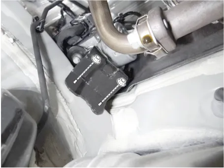
| Components |
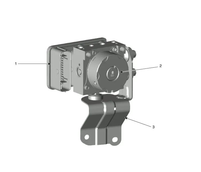
| 1. ABS control module connector 2. ABS control module | 3. ABS bracket |
Repair procedures
| Removal |
| 1. | Turn ignition OFF and disconnect the negative (-) battery cable. |
| 2. | Remove the brake fluid from the master cylinder reservoir with a syringe.
|

| 3. | Remove the air cleaner assembly.
G 1.0 MPI (Refer to Engine Mechanical System - "Air cleaner")
G 1.2 MPI (Refer to Engine Mechanical System - "Air cleaner")
F 1.0 MPI (Refer to Engine Mechanical System - "Air cleaner")
|
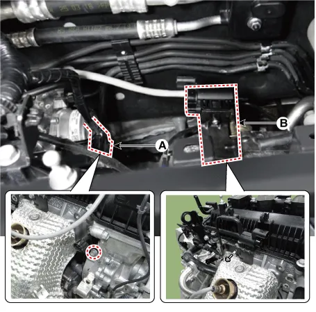
| 4. | Loosen the bolt and then remove the CVVT oil control valve bracket (A) and connector bracket (B).
|
| 5. | Disconnect the brake tubes from the ABS by unlocking the nuts counterclockwise with a wrench.
|
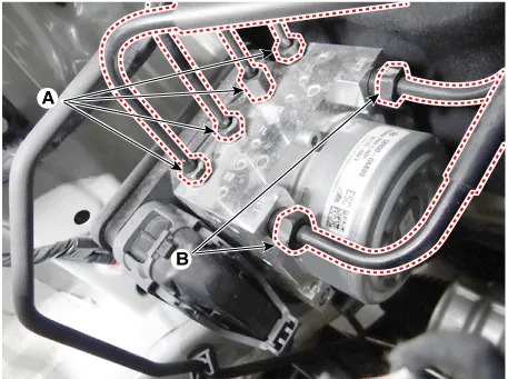
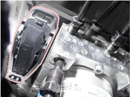
| 6. | Disconnect the ABS control module connector.
|
| 7. | Loosen the nuts and then remove the ABS control module (HECU).
|
| Installation |
| 1. | Install in the reverse order of removal. |
| 2. | After installation, bleed the brake system. |
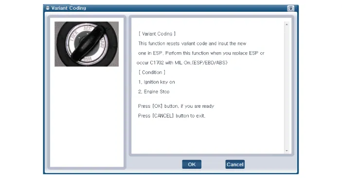
| 3. | Conduct the Variant coding. |
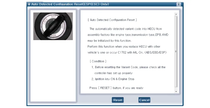
| 4. | Conduct the Auto Detected Sensor Calibration. |
| 5. | Conduct the Longitudinal G Sensor Calibration. |
| Diagnostic procedure by using diagnostic device |
| [Variant Coding] |
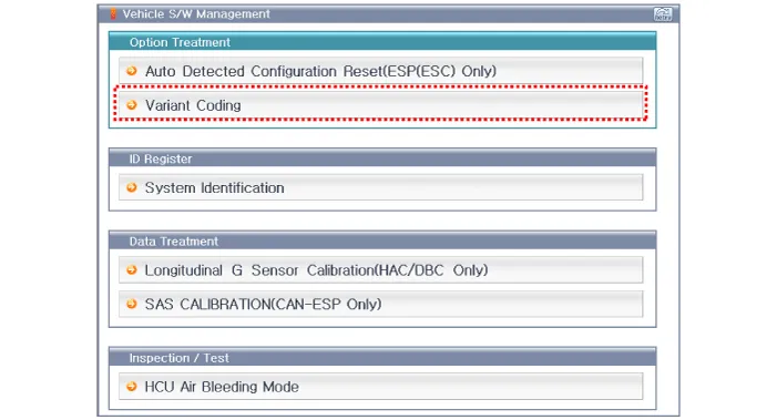
| [Auto Detected Sensor Calibration] |

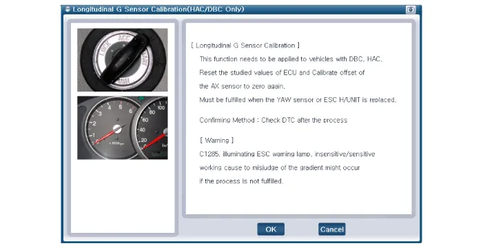
| [Longitudinal G Sensor Calibration] |

Components and components location Components 1. ABS control module (HECU) 2. Front wheel speed sensor 3. Rear wheel speed sensor Description and operation Description This specification applies to HCU(Hydraulic Control Unit) and ECU(Electronic Control Unit) of the HECU.
Repair procedures Removal 1. Remove the wheel tire (A). Tightening torque: 107.9 - 127.5 N·m (11.0 - 13.0 kgf·m, 79.6 - 94.
Other information:
Kia Picanto (JA) 2017-2026 Service & Repair Manual: Horn
Components and components location Component Location 1. Horn switch 2. Horn relay 3. Horn 4. Clock spring Repair procedures Removal 1.Disconnect the negative (-) battery terminal. 2.Remove the engine room under cover. G 1.
Kia Picanto (JA) 2017-2026 Service & Repair Manual: Front Wiper Motor
Components and components location Component Location 1. Cap 2. Nut 3. Wiper arm & blade 4. Cowl top cover 5. Bolt 6. Wiper motor & linkage assembly 7. Wiper motor connector Repair procedures Removal 1.Disconnect the negative (-) battery terminal.
Categories
- Manuals Home
- Kia Picanto Owners Manual
- Kia Picanto Service Manual
- Suspension System
- Battery
- Engine Control / Fuel System
- New on site
- Most important about car
